Industrial 3D scanning gives engineers a practical way to turn an existing physical component into usable digital engineering data, particularly when the original CAD model or technical drawings are missing. By capturing the geometry of a part and combining that data with reverse engineering, an existing component can be reconstructed as an accurate CAD model for inspection, redesign, documentation or manufacturing.
This is particularly valuable for manufacturers and operators working with legacy equipment, obsolete components or machinery that has been modified over years of service. Instead of relying solely on manual measurement or attempting to source drawings from an original manufacturer, engineers can start with the component that already exists.
The important distinction is that scanning is only the beginning. A scan produces geometric data; turning that data into a production-ready component requires engineering judgement, CAD reconstruction, dimensional validation and an understanding of how the part will ultimately be manufactured.
Why Industrial 3D Scanning Matters When Original CAD Data Is Missing
Industrial equipment can remain in service for decades. During that time, drawings can disappear, suppliers can change, manufacturers can discontinue product lines and components can be modified during repairs. Eventually, a replacement may be required for a part that exists physically but has little or no usable digital documentation.
Traditional measurement methods are still appropriate for many simple geometries. The difficulty increases when a component contains curved surfaces, complex profiles, irregular features or geometry that would require a large number of individual measurements to reproduce accurately.
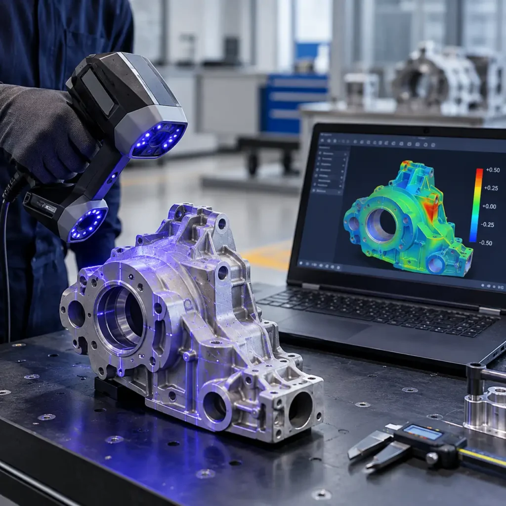
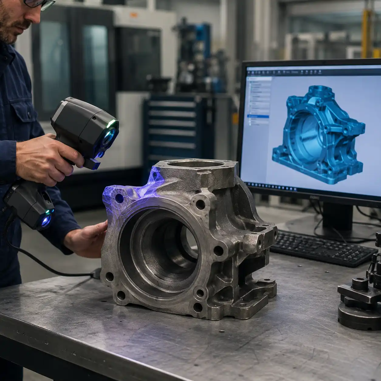
This is where industrial 3D scanning services can provide a much more complete digital representation of the existing component. A scanner captures surface geometry across the part, creating digital data that engineers can use as the foundation for further analysis and reconstruction.
Consider an older pump housing or machinery component in a mining operation. The equipment may still be operational, but the original manufacturer may no longer supply the required replacement. If a usable component is available, scanning can capture its geometry and give engineers a starting point for reconstructing the part rather than designing a replacement with no reliable dimensional reference.
For Australian companies operating equipment far from major manufacturing centres, this capability can also reduce one of the practical barriers associated with maintaining legacy assets: access to usable engineering data.
From 3D Scan to Production-Ready CAD
A common misconception is that scanning a component automatically produces a finished CAD model. In reality, there is an important engineering process between capturing a physical surface and creating a model suitable for manufacturing.
The workflow begins with the physical component. Depending on its geometry, size, surface condition and the accuracy required, the component is scanned to capture its visible surfaces. The resulting data is typically represented as a point cloud or polygon mesh that describes the measured geometry.
That scan data then becomes a reference for CAD reconstruction. Engineers identify relevant features, surfaces, holes, interfaces and functional geometry and use this information to develop a structured CAD model.
The difference matters. A worn component, for example, should not necessarily be reproduced exactly as scanned. Wear, deformation, damage or previous repairs may be present in the captured geometry. Simply copying those imperfections could reproduce the same problems in the replacement.
This is where engineering solutions become part of the workflow. The engineer must determine what represents the intended geometry, what represents service wear and which dimensions or interfaces are critical to the component’s function.
A simplified workflow looks like this:
Physical Component → 3D Scanning → Point Cloud / Mesh → CAD Reconstruction → Engineering Validation → Manufacturing Data
The final objective is therefore not simply to create a visually similar digital object. It is to create engineering data that can be used confidently for the next stage of the component’s life.
What Can Engineers Do With the Digital Model?
Once a physical component has been converted into an appropriate CAD model, its usefulness extends well beyond producing a direct copy.
The digital model can become a permanent engineering record for a component that previously existed only as a physical object. This can be particularly useful for legacy machinery, specialised tooling and low-volume components where maintaining conventional spare-parts inventory is difficult or expensive.
Engineers can also compare scan data with existing CAD information to identify dimensional differences, wear or deformation. Where a component has experienced years of service, this comparison can provide useful information about how the physical part has changed.
More importantly, reverse engineering creates an opportunity to reconsider the design rather than simply duplicate it. A recurring failure point may justify a geometry change. A component that is unnecessarily heavy may have opportunities for optimisation. Features originally designed around an old manufacturing process may also be reconsidered if a different production method is now available.
This is why reverse engineering should not be treated as digital photocopying. The objective is to understand the physical component well enough to create useful engineering information from it.
Where 3D Scanning and Reverse Engineering Are Used in Industry
The value of scanning becomes particularly clear in industries where equipment availability has a direct effect on production.
In mining, machinery is often exposed to abrasion, impact, vibration, dust and demanding operating conditions. Some assets remain operational long after their original component supply chains have changed. When a replacement is difficult to source, scanning an existing component can provide the geometric information needed to assess whether a replacement can be reverse engineered and manufactured.
This can be relevant to mining equipment and components such as housings, brackets, covers, interfaces, specialised fittings and other low-volume parts where conventional replacement channels are limited or slow. It does not mean every scanned component is suitable for reproduction; material requirements, loading, tolerances and safety implications still need to be assessed.
Manufacturing presents a different set of opportunities. Existing tooling, fixtures, legacy machine components and physical prototypes may need to be digitised for modification, inspection or reproduction. In these situations, advanced manufacturing applications can combine scanning with CAD engineering to bridge the gap between physical assets and modern digital production systems.
The same principle can extend into sectors such as oil and gas, where older equipment and specialised components may present similar documentation challenges. The specific engineering requirements, however, depend heavily on the component, its operating environment and applicable standards.
When Does the Workflow Continue to Metal 3D Printing?
Reverse engineering does not automatically mean that a component should be additively manufactured.
Once a production-ready CAD model exists, engineers can evaluate the most appropriate manufacturing method based on geometry, material, quantity, tolerances, component size, required properties, lead time and economics. Conventional machining may remain the better option for many parts.
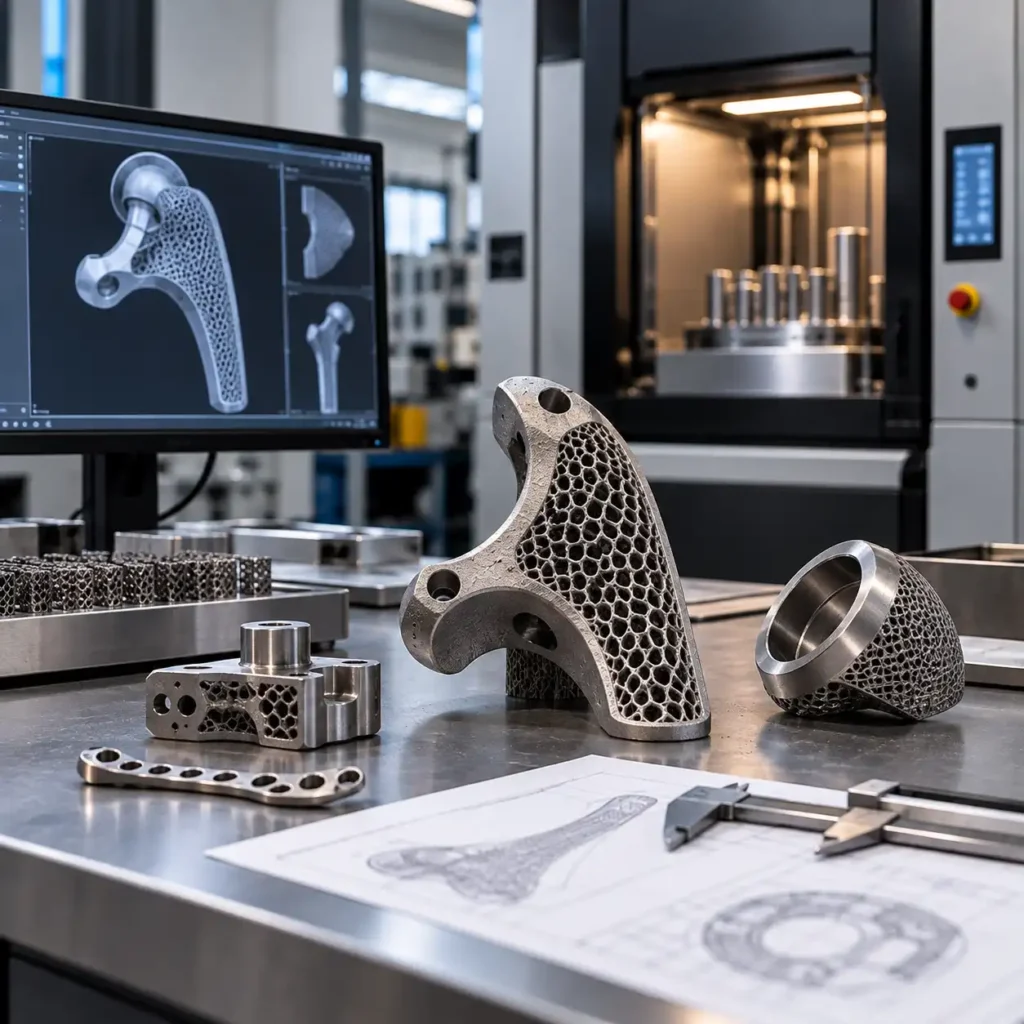
However, metal 3D printing becomes particularly interesting when the component is complex, required in low quantities, difficult to source through an existing supply chain or presents an opportunity for redesign.
Additive manufacturing can also change the question from “How do we reproduce this part?” to “How should this part be designed if we manufacture it differently?”
A component originally designed for casting or subtractive machining may contain features dictated by those manufacturing methods. Once the geometry has been reconstructed digitally, engineers can assess whether design changes could consolidate parts, alter internal geometry, reduce material or address known performance issues.
This combination of scanning, reverse engineering and additive manufacturing is particularly relevant to digital spare-parts strategies. Instead of treating every replacement as an item that must permanently occupy warehouse space, suitable components can potentially exist as controlled digital engineering data until manufacturing is required.
That transition requires careful engineering and quality control, but it represents a significant change in how industrial organisations can think about low-volume and difficult-to-source components.
3D Scanning Is the Starting Point, Not the Final Result
The real value of industrial 3D scanning is not the point cloud itself. It is the engineering work that becomes possible once a physical component has been converted into reliable digital information.
For a simple inspection task, scan data may be enough. For reverse engineering, the workflow continues into CAD reconstruction and validation. For a replacement component, material selection and manufacturing requirements must also be considered. If the objective is to improve the original design, engineering analysis becomes even more important.
In practical terms, the progression is:
Physical Part → Digital Data → Engineering Knowledge → Manufacturable Component
For Australian industrial companies managing legacy equipment, specialised components or incomplete engineering documentation, this creates a practical route from an existing physical asset back into a modern digital manufacturing workflow.
E-Metal3D provides 3D scanning and engineering capabilities for industrial applications where existing components need to be digitised, evaluated or reconstructed. Where appropriate, that workflow can continue through engineering development and metal additive manufacturing rather than ending with the scan itself.
What is industrial 3D scanning used for?
Industrial 3D scanning is used to capture the geometry of physical components and equipment as digital data. The resulting scan can support dimensional inspection, reverse engineering, CAD reconstruction, documentation, redesign and manufacturing workflows.
Can a 3D scan be converted into a CAD model?
Yes, but a scan is not automatically a production-ready CAD model. Scan data such as a point cloud or mesh can be used as a reference for CAD reconstruction, after which the model may require engineering validation before it is suitable for manufacturing.
Can 3D scanning be used when the original drawings are missing?
Yes. This is one of the most useful applications of 3D scanning and reverse engineering. An existing physical component can provide the geometric reference needed to reconstruct digital engineering data when original CAD files or drawings are unavailable.
Can a worn component be reverse engineered?
Potentially, but the scanned geometry should not automatically be reproduced exactly. Engineers need to identify wear, damage, deformation and critical functional features so that the reconstructed model represents the required component rather than simply copying its current condition.
Can a reverse-engineered component be metal 3D printed?
In suitable cases, yes. Once a validated CAD model has been developed, metal 3D printing can be evaluated alongside conventional manufacturing methods. The appropriate process depends on factors including material, geometry, quantity, tolerances, mechanical requirements and economics.