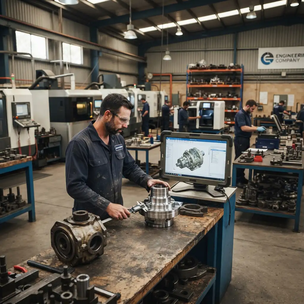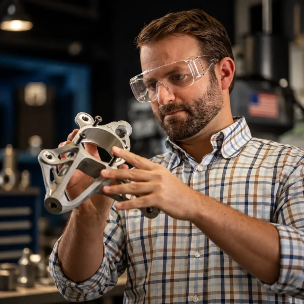
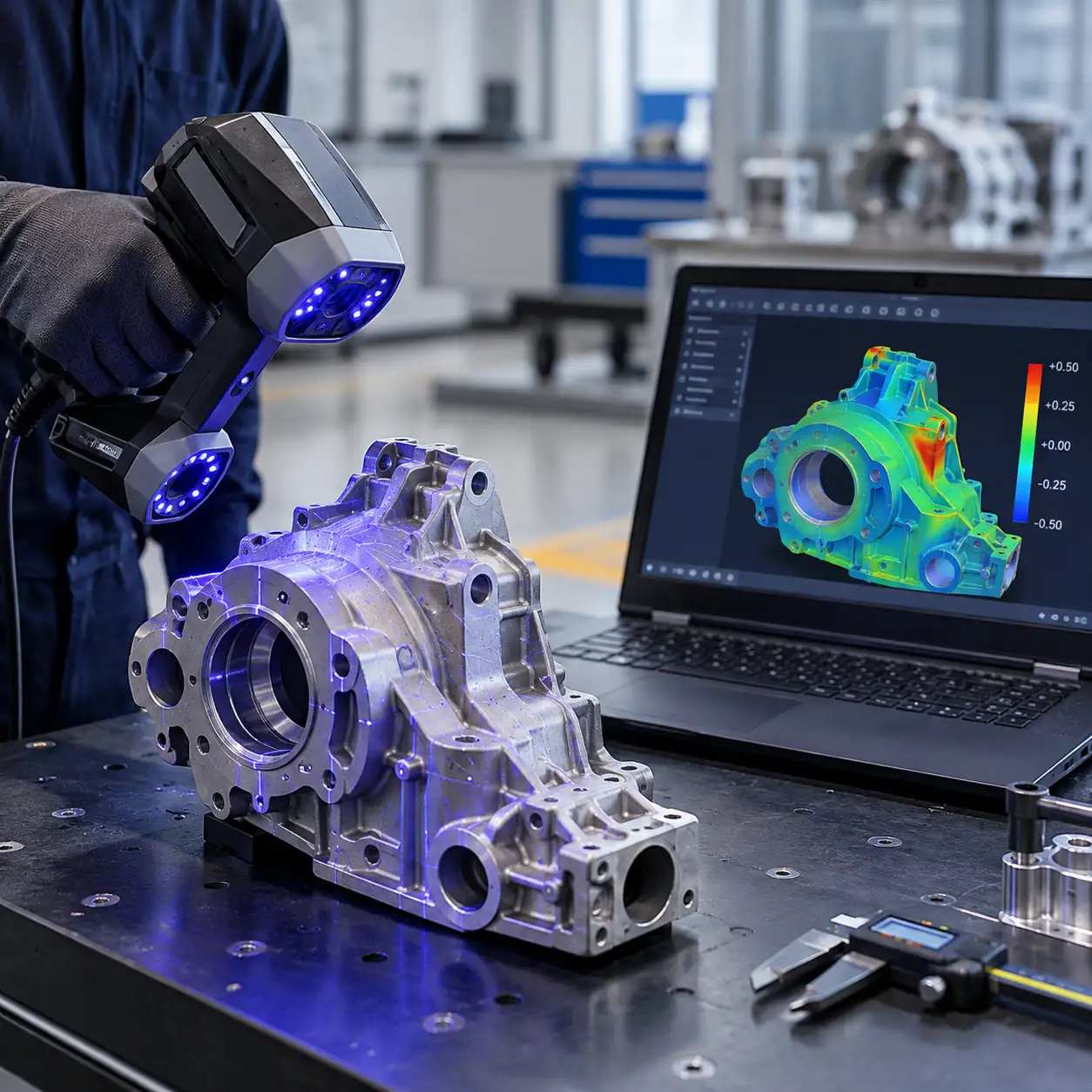
3D dimensional inspection in Australia helps manufacturers and engineering teams determine whether a physical component matches its intended design, dimensional requirements and functional geometry. By combining industrial 3D scanning with CAD comparison and established metrology practices, engineers can investigate geometric deviations, verify complex surfaces and make more informed decisions about component acceptance, rework and manufacturing quality.
For Australian industries such as mining, manufacturing, energy and industrial equipment maintenance, dimensional accuracy can directly influence assembly, reliability and component interchangeability. A replacement part may appear visually identical to the original but still contain geometric differences that affect its fit or operation.
Three-dimensional inspection provides a detailed representation of the measured component, making it possible to assess geometric characteristics that may be difficult to evaluate using conventional hand tools alone.
However, scanning a component is not equivalent to proving that it meets every engineering requirement. Reliable dimensional inspection depends on measurement accuracy, appropriate equipment, datum alignment, uncertainty, inspection planning and the correct interpretation of results.
What Is 3D Dimensional Inspection?
3D dimensional inspection is the process of measuring and evaluating the geometry of a physical object against defined dimensional requirements.
In industrial applications, those requirements may originate from an engineering drawing, a nominal CAD model, a geometric dimensioning and tolerancing (GD&T) specification or an approved reference component.
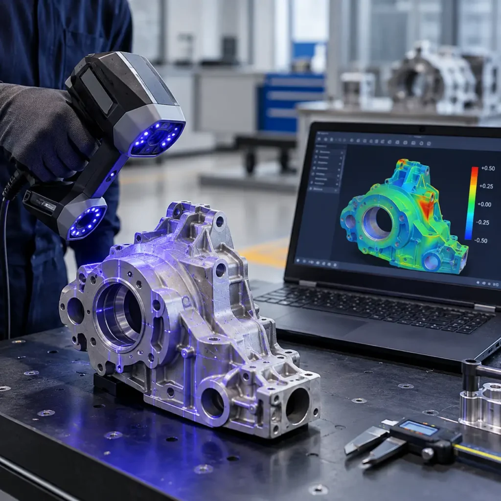
Unlike conventional measurements that examine selected dimensions individually, some 3D scanning systems capture extensive surface geometry. This allows engineers to investigate the overall shape of a component and identify areas where the manufactured geometry differs from its nominal design.
A typical inspection process may involve acquiring measurement data, aligning it with a reference model, evaluating relevant geometric features and producing an inspection report.
The purpose is not simply to create a digital model. It is to generate measurement evidence that supports engineering decisions.
Dimensional Inspection Versus 3D Scanning
Although closely related, these activities serve different purposes.
3D scanning captures the physical geometry of an object and generates digital measurement data, commonly represented as a point cloud or polygon mesh.
Dimensional inspection evaluates whether the measured geometry satisfies specified engineering requirements.
A scan can provide the measurement data required for inspection, but the inspection process must also establish how measurements are interpreted, which features are relevant and whether the measurement system is suitable for the tolerances involved.
This distinction is particularly important for components with critical fits, sealing interfaces, bearing locations or assembly features.
Why Dimensional Inspection Matters in Industrial Manufacturing
Manufacturing processes introduce variation. Machining, casting, welding, heat treatment and metal additive manufacturing can all affect the geometry of a finished component.
The amount and nature of that variation depend on the process, material, component design and manufacturing conditions.
For example, a machined housing may contain a local dimensional deviation, while a fabricated assembly may exhibit distortion caused by welding. An additively manufactured component may experience thermal distortion, surface roughness or geometric changes during post-processing.
Not every deviation makes a component unacceptable. Engineering drawings and specifications define the permissible limits for relevant characteristics.
Dimensional inspection helps determine whether those limits have been satisfied.
For manufacturers, this can support first-article inspection, production quality control, supplier verification, process improvement and investigation of nonconforming parts.
For maintenance and reliability teams, inspection can also provide evidence about geometric changes in equipment components, although determining the cause or operational significance of those changes may require additional engineering analysis.
How Industrial 3D Scanning Supports Quality Control
Industrial 3D scanning can provide dense geometric information that would be time-consuming to acquire through individual manual measurements.
Depending on the technology, a scanning system may capture the component surface using structured light, laser-based techniques or other optical measurement methods.
The resulting data can be processed into a digital representation suitable for geometric evaluation.
However, the choice of scanning system must reflect the inspection task.
Structured-Light Scanning
Structured-light systems project a known light pattern onto an object and use cameras to calculate surface geometry from the observed pattern deformation.
These systems can be useful for capturing complex external surfaces, including castings, machined components and industrial parts with irregular geometry.
Their suitability depends on factors such as component size, surface properties, environmental conditions, system calibration and required measurement uncertainty.
Reflective, transparent or very dark surfaces may require special handling, depending on the equipment.
Laser-Based 3D Scanning
Laser-based scanning systems use projected laser light and optical sensing to measure surface geometry.
Some systems are designed for handheld operation, while others are integrated into measurement arms or automated inspection arrangements.
They can be useful for industrial components where portability, access or complex geometry makes conventional measurement challenging.
Nevertheless, a scanner’s published accuracy specification should not automatically be treated as the uncertainty of every measurement performed with it.
The complete measurement setup and procedure must be considered.
Coordinate Measuring Machines
Coordinate measuring machines (CMMs) are widely used in industrial dimensional metrology.
A CMM may use tactile probing, optical sensors or other measurement technologies to evaluate geometric characteristics.
For certain precision features, a suitable CMM measurement strategy may be more appropriate than general-purpose surface scanning.
In practice, optical scanning and CMM measurement can complement one another.
A broad surface scan may reveal the overall geometry, while targeted measurements provide additional evidence for critical features.
The 3D Dimensional Inspection Workflow
A useful inspection workflow begins with engineering requirements rather than with the scanner.
1. Define Inspection Requirements
Drawing, CAD, datums, tolerances and critical features
2. Plan and Capture Measurements
Equipment, calibration, access, surface preparation and measurement strategy
3. Process and Align Data
Point cloud or mesh processing, datum-based alignment and registration checks
4. Evaluate Geometry
CAD deviations, selected dimensions, GD&T characteristics and uncertainty
5. Report and Decide
Document results, identify nonconformities and support engineering disposition
Step 1: Establish the Inspection Requirements
Before scanning, engineers should identify what must be verified.
An engineering drawing may specify dimensional tolerances, datum features, surface requirements and geometric controls.
These requirements determine the measurement strategy.
For example, inspecting the overall shape of a cast pump housing is different from verifying a tightly toleranced bearing bore.
A dense surface scan may be suitable for evaluating the casting geometry, while the bearing bore may require a separate precision measurement.
Step 2: Prepare the Component and Measurement Setup
The component should be accessible, stable and appropriately prepared for measurement.
Preparation may include cleaning the surface, controlling environmental conditions, selecting suitable fixturing and confirming the scanner’s calibration status.
The influence of surface treatment must also be considered. For example, applying scanning spray can change the measured surface, which may be significant when tight tolerances are involved.
Inspection planning should account for measurement uncertainty and the intended acceptance criteria.
Step 3: Capture and Process Measurement Data
The selected measurement system captures the relevant geometry.
For optical scanning, multiple views may be required to cover complex surfaces.
Data processing can include registration, filtering and mesh generation.
Excessive smoothing or inappropriate processing can obscure real geometric deviations. Processing choices should therefore be consistent with the inspection requirements.
Step 4: Align the Measured Data with the Reference
The measured geometry is aligned with the nominal CAD model or other approved reference.
This stage requires particular attention because different alignment methods can produce different deviation patterns.
For example, best-fit alignment seeks an overall mathematical fit between measured and nominal geometry. It can be useful for evaluating certain freeform surfaces.
However, best-fit alignment is not automatically appropriate for assessing a component against drawing-defined datum requirements.
Where the engineering specification establishes a datum reference frame, inspection should respect that frame.
Step 5: Evaluate Deviations and Prepare the Report
Inspection software can calculate differences between measured and nominal geometry.
The report may include colour deviation maps, selected dimensional measurements, geometric evaluations and identified areas of concern.
Results should be interpreted against specified tolerances and measurement uncertainty.
A component should not be declared conforming solely because a colour map appears predominantly green.
Understanding CAD-to-Scan Deviation Analysis
One of the most useful applications of industrial 3D scanning is comparing a manufactured component with its nominal CAD model.
The measured surface is evaluated against the corresponding design geometry.
Inspection software may display the differences as a colour deviation map.
Nominal CADIntended geometry
Measured surfaceIllustrative local deviation
Conceptual comparison only. Not actual measurement data or a validated inspection result.
Colour maps can help engineers identify areas of positive or negative deviation, local distortion and unexpected geometric differences.
However, a deviation map is not a complete GD&T inspection report.
For example, an overall surface comparison may not establish whether a hole pattern meets positional tolerance relative to specified datums.
Similarly, a surface scan may not capture inaccessible internal geometry.
For this reason, CAD-to-scan analysis should be combined with feature-specific measurements when necessary.
Dimensional Inspection of Metal 3D Printed Components
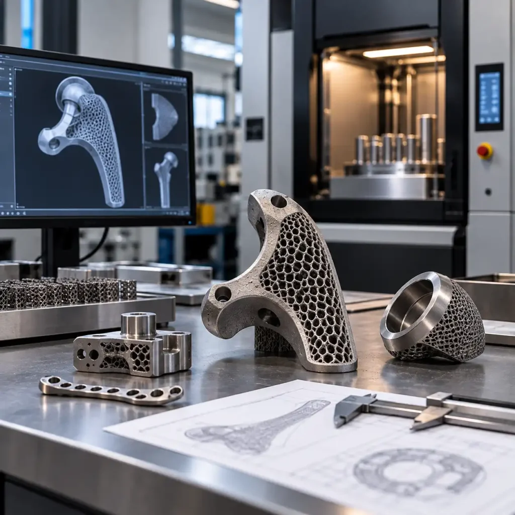
Metal additive manufacturing creates components through a fundamentally different process from conventional subtractive machining.
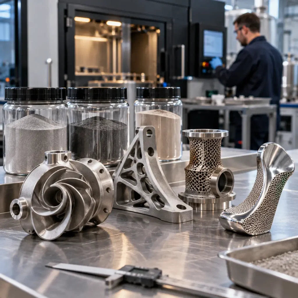
In laser powder bed fusion (LPBF), components are built layer by layer through the selective melting of metal powder.
This process enables complex geometries, internal channels and integrated features, but it also introduces inspection challenges.
Potential considerations include thermal distortion, support-removal effects, as-built surface condition, residual material in internal passages and dimensional changes during subsequent processing.
3D scanning can help evaluate accessible external geometry before and after post-processing.
For example, an engineer may compare a printed component with the nominal CAD model to identify geometric deviations before deciding whether additional machining or other corrective work is necessary.
However, surface scanning cannot verify every quality characteristic of an additively manufactured component.
Internal porosity, lack-of-fusion defects and inaccessible internal features may require other inspection methods, potentially including industrial computed tomography or appropriate non-destructive testing.
Material properties and process qualification also require separate evidence.
A sound inspection strategy therefore considers the component’s intended application, not simply whether its external shape matches the CAD file.
Applications in Australian Mining and Industrial Equipment
Mining equipment often operates under demanding mechanical and environmental conditions.
Replacement components may need to interface with existing assemblies, and dimensional differences can affect fit or function.
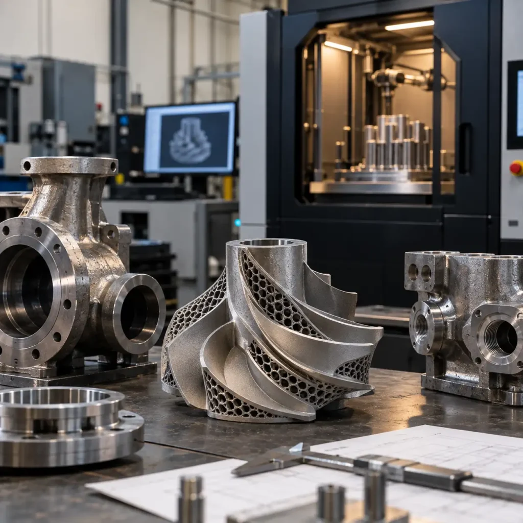
Industrial 3D dimensional inspection can support the evaluation of pump housings, equipment brackets, fabricated assemblies, replacement castings and other accessible mechanical components.
For example, consider a replacement pump housing manufactured from an existing engineering model.
Before installation, engineers may need to verify mounting locations, flange interfaces and other critical features.
A combination of surface scanning and targeted dimensional measurement can provide useful evidence about whether the manufactured component conforms to the applicable specifications.
This is particularly relevant when equipment has undergone multiple repairs or modifications over its service life.
Nevertheless, inspection results must be interpreted against approved engineering requirements. Matching the geometry of a worn original component is not necessarily equivalent to restoring the correct design.
Dimensional Inspection for Reverse Engineering
Dimensional inspection and reverse engineering frequently use similar measurement technologies, but their objectives differ.
Reverse engineering generally seeks to reconstruct or understand a component’s design from physical evidence.
Dimensional inspection evaluates the geometry of a component against defined requirements.
For obsolete industrial components, the two activities may be connected.
An engineering team may scan an existing part, reconstruct its CAD geometry and manufacture a replacement.
The newly manufactured component can then be inspected against the approved reconstructed design.
This creates a workflow linking physical measurement, engineering interpretation, manufacturing and quality verification.
However, the reconstructed CAD model should not automatically be considered the original design intent.
Wear, deformation, previous repairs and manufacturing variation can all influence the geometry captured from an existing part.
Engineering review is necessary before that geometry becomes the manufacturing reference.
Choosing Between 3D Scanning and Conventional Metrology
No single measurement technology is appropriate for every inspection requirement.
The selection should depend on the component, specified tolerances, surface characteristics, accessibility and required measurement uncertainty.
| Inspection requirement | Potentially suitable approach |
|---|---|
| Complex external casting geometry | Industrial optical 3D scanning |
| High-precision accessible bore | Suitable CMM or precision bore measurement |
| Overall fabricated assembly shape | Large-volume 3D measurement or scanning |
| Freeform surface comparison | 3D scanning with CAD analysis |
| Critical datum-related GD&T features | Qualified feature-specific measurement strategy |
| Internal geometry not optically accessible | Appropriate internal measurement or NDT method |
These are general examples, not universal equipment-selection rules.
The correct method must be selected according to the required uncertainty and inspection specification.
In some cases, combining methods provides more reliable evidence than relying on a single system.
Measurement Accuracy, Repeatability and Uncertainty
Measurement accuracy is a critical consideration in industrial inspection, but it is not the only one.
Repeatability describes how consistently a measurement process produces results under defined conditions.
Measurement uncertainty describes the range of values reasonably attributable to the measurand, based on the available information and uncertainty contributors.
These concepts are related but not interchangeable.
A scanner may produce repeatable results while still containing systematic measurement error.
Similarly, an equipment specification may describe performance under controlled test conditions that differ from those encountered in a particular industrial inspection.
Important influences can include calibration, environmental conditions, surface characteristics, operator technique, alignment strategy, fixturing and data-processing choices.
For tolerance-critical applications, measurement uncertainty should be considered when making conformity decisions.
The applicable acceptance or rejection rule should be agreed upon and documented, particularly where results are close to tolerance boundaries.
What Should an Industrial Dimensional Inspection Report Include?
A useful inspection report should provide enough information for engineers and quality personnel to understand what was measured, how it was evaluated and what conclusions are supported.
Depending on the inspection scope, relevant information may include the component identification, drawing or CAD revision, measurement equipment, calibration status, inspection method, datum alignment, measured characteristics, specified tolerances, results and relevant uncertainty information.
Deviation visualisations can help communicate complex geometry, but numerical results and traceable references are often necessary for formal engineering decisions.
The report should also identify any limitations, such as inaccessible surfaces or features that were not evaluated.
This prevents a partial geometric inspection from being misinterpreted as complete component qualification.
When 3D Scanning Is Not the Right Inspection Method
3D scanning offers significant advantages for complex surface measurement, but it is not always the most appropriate choice.
For simple dimensions, conventional measuring instruments may provide faster and more economical results.
For tightly toleranced features, a suitable precision measurement method may offer a more appropriate uncertainty.
Optical scanning may also be limited by inaccessible surfaces, highly reflective materials, deep cavities or environmental conditions.
Furthermore, surface scanning cannot establish mechanical properties, chemical composition, fatigue performance or internal material integrity.
These characteristics require separate testing or verification.
An effective quality-control process selects measurement methods based on the engineering requirement rather than using scanning for every feature.
Integrating Dimensional Inspection into Manufacturing Quality Control
Dimensional inspection provides the greatest value when it is integrated into the manufacturing workflow rather than treated only as a final check.
During product development, early measurements can reveal geometric problems before a design is finalised.
During first-article inspection, measurements can help establish whether the manufacturing process produces parts that meet specified requirements.
During ongoing production, selected inspections can support process monitoring and investigation of manufacturing variation.
For replacement and obsolete components, inspection can help verify that the manufactured part matches an approved engineering definition before it enters service.
When inspection identifies a deviation, the next step is engineering evaluation.
A deviation may require rework, additional measurement, design review or rejection. In some cases, a formal concession or deviation approval process may be appropriate.
The inspection system provides evidence; it does not replace engineering judgement.
Industrial 3D Scanning and Engineering Support in Australia
Australian industrial organisations may require dimensional measurement as part of reverse engineering, replacement component development, manufacturing verification or broader engineering investigations.
For projects involving complex components, the ability to connect scanning data with CAD reconstruction and manufacturing decisions can be particularly useful.
E-Metal3D provides industrial 3D scanning and engineering solutions that can support physical-to-digital workflows, reverse engineering and component development.
Where a project requires formal dimensional inspection, the measurement scope, tolerances, equipment suitability, reporting requirements and verification responsibilities should be established before work begins.
For components intended for metal additive manufacturing, inspection planning should also account for manufacturing orientation, accessible surfaces, post-processing and any critical features requiring separate verification.
Explore E-Metal3D’s 3D Scanning Services and Engineering Solutions to discuss the measurement and engineering requirements of an industrial component.
Conclusion
Industrial 3D dimensional inspection provides a valuable connection between digital engineering designs and manufactured physical components.
By combining appropriate 3D scanning technologies with CAD comparison, dimensional metrology and engineering interpretation, manufacturers can gain a more detailed understanding of geometric conformity and manufacturing variation.
The central consideration is not how much surface data can be captured, but whether the inspection process produces reliable evidence for the dimensions and features that matter.
For Australian manufacturers and industrial maintenance teams, selecting the right measurement strategy can support better quality decisions, more effective reverse engineering and more reliable component development.
What is 3D dimensional inspection?
3D dimensional inspection is the measurement and evaluation of a physical component’s geometry against specified engineering requirements. It may use 3D scanning, CMMs or other measurement technologies.
Can 3D scanning replace a coordinate measuring machine?
Not in every application. 3D scanning is useful for many complex surface measurements, while CMMs and other precision systems may be more appropriate for particular tightly toleranced features. The selection depends on the measurement task and required uncertainty.
How accurate is industrial 3D scanning?
Accuracy depends on the equipment, measurement volume, surface conditions, calibration, alignment and inspection method. A system’s published accuracy specification does not automatically establish the uncertainty of a particular measurement.
Can 3D scanning inspect metal 3D printed parts?
Yes. It can help evaluate accessible external geometry, including dimensional deviations and distortion. It cannot independently verify all internal defects, material properties or mechanical performance.
What is the difference between dimensional inspection and reverse engineering?
Dimensional inspection evaluates a component against defined requirements. Reverse engineering reconstructs or analyses design information from an existing physical component. Both may use 3D scanning.
Can a 3D scan identify manufacturing defects?
A scan may reveal surface or geometric deviations, but not all manufacturing defects. Internal porosity, material discontinuities and certain subsurface defects require other appropriate inspection methods.
What information is needed before dimensional inspection?
Useful inputs include an approved CAD model or engineering drawing, relevant tolerances, datum requirements, component condition, inspection objectives and any specific reporting or traceability requirements.