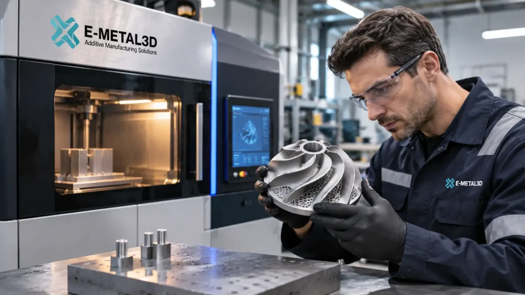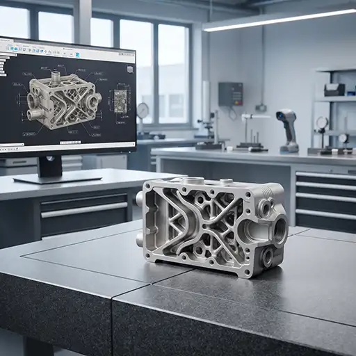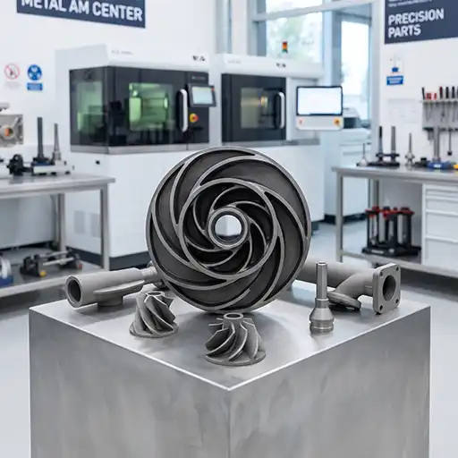
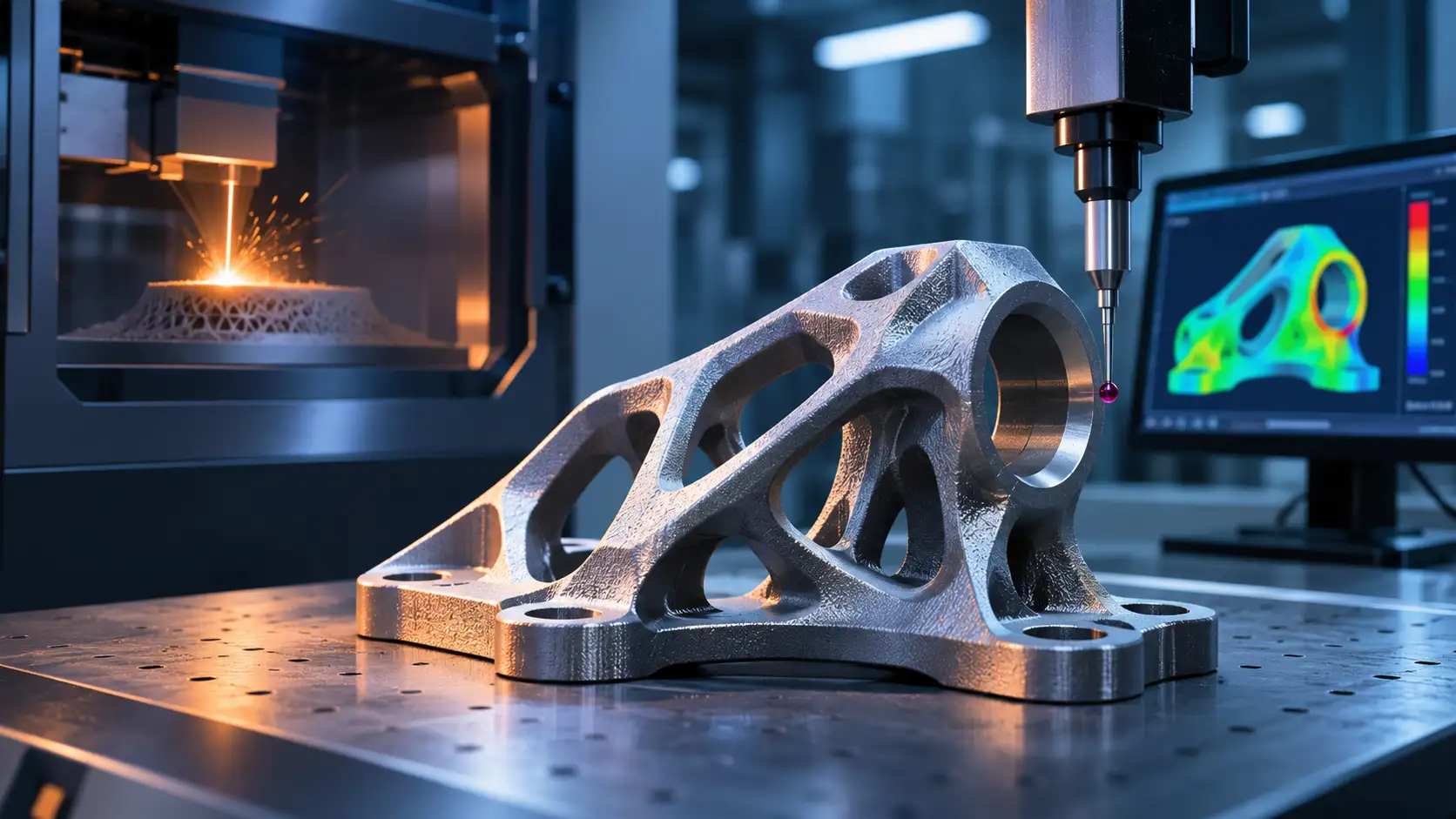
Metal 3D printing quality control is not simply a final inspection performed after a component leaves the printer. For industrial applications, it is a coordinated process involving material verification, build preparation, process monitoring, post-processing, dimensional inspection and evidence that the finished part meets its intended requirements.
A metal component may look dimensionally correct while containing internal porosity, insufficiently fused regions or surface conditions that affect fatigue performance. Equally, a part may be manufactured successfully but still fail to meet the tolerances, documentation or acceptance criteria required by its application.
For Australian manufacturers working with complex components, specialised spare parts and low-volume production, understanding how metal additive manufacturing quality is assessed is essential to making informed engineering and procurement decisions.
The objective is not to inspect every printed component in exactly the same way. It is to establish an appropriate level of quality assurance based on the part’s function, material, manufacturing process and consequences of failure.
Why Quality Control Matters in Metal Additive Manufacturing
Metal additive manufacturing offers significant design freedom, particularly through Laser Powder Bed Fusion (LPBF), which builds metal components layer by layer from powder.
However, the same process flexibility that enables complex geometries also introduces variables that must be controlled.
Powder characteristics, laser parameters, build orientation, thermal history, support design, shielding conditions and post-processing can all influence the finished component.
Potential quality concerns include:
- Internal porosity and lack-of-fusion defects
- Dimensional deviations and distortion
- Surface roughness and partially fused particles
- Residual stresses and microstructural variation
- Inconsistent mechanical properties
- Defects in internal channels or inaccessible features
- Insufficient traceability between the finished part and its manufacturing records
Not every deviation makes a component unsuitable. The engineering question is whether the observed condition exceeds the acceptance criteria established for its intended service.
A non-critical prototype and a fatigue-loaded industrial component may require very different inspection and testing strategies.
This is why quality control must begin with an understanding of the application rather than a generic promise of high precision.
1. Quality Begins with the Metal Powder
The quality of a metal 3D printed component begins before the first layer is produced.
In LPBF, metal powder must spread consistently across the build area and respond predictably to the selected processing conditions.
Relevant powder characteristics may include particle size distribution, morphology, flow behaviour, chemical composition and contamination levels.
These properties can affect powder spreading, melt behaviour and ultimately the consistency of the manufactured material.
Powder management also becomes important when unused powder is recovered and reused.
Depending on the alloy and process, reuse may require controls over contamination, oxygen exposure, powder condition, blending and traceability.
A robust material-control approach can include:
- Identifying powder batches and suppliers
- Verifying relevant material specifications
- Establishing storage and handling procedures
- Recording powder reuse where applicable
- Defining acceptance criteria for feedstock condition
The appropriate controls depend on the material, equipment and quality requirements.
Standards such as ISO/ASTM 52907 address methods for characterising metallic powder feedstock, while ASTM F3592 provides guidance related to powder reuse and sampling strategies.
For engineers comparing stainless steels, nickel alloys, titanium and other materials, powder quality should be considered alongside the nominal alloy specification.
2. Build Preparation Is Part of Quality Assurance
A technically sound CAD model is not automatically ready for metal additive manufacturing.
Before production, engineers must evaluate whether the component can be manufactured consistently and whether its critical features can be verified after printing.
Build preparation may involve assessing:
- Part orientation and support structures
- Minimum feature dimensions
- Thermal distortion risk
- Critical surfaces and machining allowances
- Powder removal from internal cavities
- Accessibility for inspection
- Material and process compatibility
Orientation can influence support requirements, surface condition and the distribution of manufacturing-induced effects.
An internal passage that is geometrically possible to print may still be difficult to clean or inspect.
Similarly, a component with tight interface tolerances may require additional machining after printing.
These considerations should be resolved before production wherever practical.
For a more detailed explanation of the design stage, see our Design for Metal Additive Manufacturing engineering guidelines and practical CAD preparation checklist.
3. In-Process Monitoring: What Happens During Printing?
In-process monitoring aims to identify or record conditions that may indicate changes in build quality.
Depending on the equipment and monitoring system, this may include information about the powder bed, melt pool, optical emissions, thermal behaviour or machine operating conditions.
These measurements can help engineers investigate process consistency and identify potentially abnormal events.
However, monitoring data must be interpreted carefully.
A stable monitoring signal does not automatically prove that a finished component is free from internal defects. Likewise, an unusual signal does not always establish that a part is unacceptable.
The relationship between monitored conditions and final material properties must be established through appropriate validation.
The US National Institute of Standards and Technology (NIST) has examined the role of in-process monitoring and non-destructive evaluation in the qualification of metal additively manufactured components.
Its research highlights both the potential value of monitoring and the challenges involved in using it as reliable evidence of final part quality.
For critical applications, process monitoring should therefore be treated as one part of a wider quality assurance strategy rather than a complete substitute for post-build inspection.
4. Dimensional Inspection: Does the Part Match the Design?
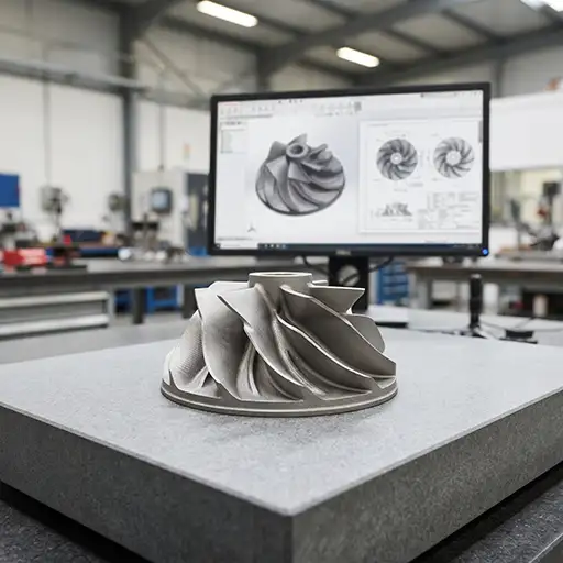
Dimensional inspection establishes whether the manufactured geometry meets the relevant drawing or model requirements.
This is particularly important for components with mounting interfaces, mating surfaces, internal channels or tight assembly constraints.
Inspection methods may include:
- Calipers and micrometers for suitable accessible features
- Coordinate Measuring Machines (CMMs)
- Optical or structured-light 3D scanning
- Surface measurement equipment
- Industrial computed tomography for selected internal geometries
The correct method depends on feature accessibility, required uncertainty, tolerance and component geometry.
For example, external freeform surfaces may be assessed through 3D scanning, while a critical bore may require a different measurement method.
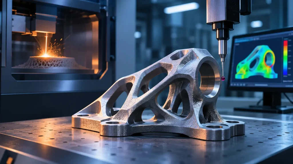
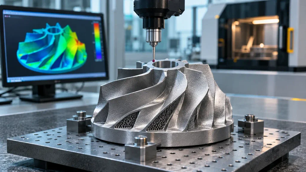
A colour deviation map can help visualise differences between a scanned component and its nominal CAD model. However, the inspection method and measurement uncertainty must still be appropriate for the acceptance decision.
Our article on industrial 3D dimensional inspection in Australia explores this subject in greater detail.
For projects requiring digitisation or geometry capture, 3D scanning services can also support engineering and inspection workflows.
5. Internal Defects: Porosity, Lack of Fusion and CT Inspection
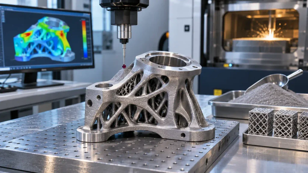
Some of the most important quality characteristics of metal 3D printed components cannot be assessed through visual inspection alone.
LPBF components may contain internal discontinuities arising from different mechanisms.
Examples include gas-related pores, lack-of-fusion regions and voids associated with unstable melting conditions.
Their significance depends on characteristics such as size, shape, location, orientation and the loads experienced by the component.
A small discontinuity in a lightly loaded region may have different consequences from a similar defect near a highly stressed surface.
Industrial Computed Tomography
Industrial computed tomography (CT) uses X-ray measurements to reconstruct information about a component’s internal structure.
For suitable parts, CT can help identify internal voids, examine inaccessible passages and compare selected internal features with the nominal geometry.
However, CT is not a universal solution.
Detection capability depends on material, part thickness, geometry, equipment settings, image quality and the defect characteristics being investigated.
Dense materials and thick sections may be particularly challenging.
CT results also require suitable evaluation criteria. Detecting a discontinuity is not the same as proving that the part is unsuitable.
Other Non-Destructive Testing Methods
Depending on the component and application, alternative or complementary techniques may include:
- Dye penetrant testing for suitable surface-breaking discontinuities
- Radiographic testing
- Ultrasonic testing where geometry and material conditions permit
- Visual inspection
- Other application-specific non-destructive evaluation methods
No single inspection method detects every relevant defect.
Organisations such as TWI emphasise the importance of selecting inspection techniques according to the component and its quality requirements.
6. Mechanical Testing: Beyond Geometry and Appearance
A component can meet its dimensional requirements and still lack the mechanical properties needed for service.
Mechanical testing provides evidence about how the manufactured material behaves under specified conditions.
Depending on the application, relevant tests may include:
- Tensile testing
- Hardness testing
- Fatigue testing
- Impact testing
- Density measurement
- Metallographic examination
Testing requirements should be established from the part specification, material requirements and intended operating conditions.
For example, a component subjected to repeated cyclic loads may require particular attention to fatigue behaviour.
Surface roughness, internal discontinuities, microstructure, residual stresses and post-processing can all influence fatigue performance.
Test coupons may be produced to assess particular material or build characteristics, but their relevance to the finished component depends on the qualification strategy.
A coupon result should not automatically be treated as proof that every feature of a complex component has identical properties.
For demanding applications, representative testing and documented acceptance criteria are essential.
7. Post-Processing Can Change Final Part Quality
Metal 3D printing does not always produce a finished, installation-ready component directly from the build chamber.
Post-processing may be required to achieve the specified material condition, surface finish, dimensional accuracy or cleanliness.
Typical operations can include:
- Support removal
- Stress-relief heat treatment
- Heat treatment appropriate to the alloy
- Hot Isostatic Pressing (HIP), where justified
- CNC machining of critical interfaces
- Surface finishing
- Cleaning and powder removal
- Final dimensional inspection
Each operation can influence the final component.
For example, machining may improve the dimensional accuracy and surface condition of a sealing face or precision bore.
Heat treatment may alter microstructure and mechanical properties.
HIP can reduce certain internal voids in suitable materials and conditions, but it should not be assumed to eliminate every defect or guarantee fatigue performance.
Post-processing must therefore be included in the quality plan rather than treated as an optional finishing step.
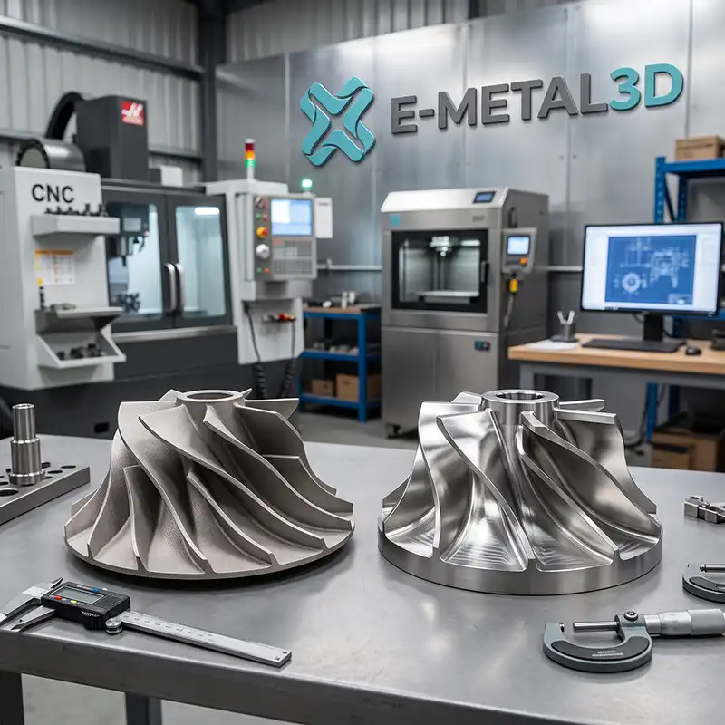
This is one reason why metal additive manufacturing and CNC machining are often complementary technologies.
Our comparison of metal 3D printing versus CNC machining explains when each process offers an advantage.
8. Traceability: Knowing How a Part Was Manufactured
Traceability becomes increasingly important when components are produced for demanding industrial environments.
A quality record may need to connect the finished part to the information used to manufacture and verify it.
Depending on the agreed requirements, this can include:
| Record | Why It Matters |
|---|---|
| Drawing or CAD revision | Identifies the approved design |
| Material and powder batch | Supports material traceability |
| Machine and build identification | Links the part to its production history |
| Process documentation | Records relevant manufacturing conditions |
| Heat-treatment records | Documents the specified thermal processing |
| Inspection results | Provides evidence of dimensional or defect acceptance |
| Test reports | Records relevant material or mechanical test results |
| Nonconformance records | Documents deviations and their disposition |
Not every project requires the same documentation package.
A prototype intended for early design evaluation may need fewer records than a safety-critical production component.
The important principle is to agree on documentation and acceptance requirements before manufacturing begins.
9. What Do ISO and ASTM Standards Say About Metal AM Quality?
International standards provide a useful framework for understanding quality assurance in additive manufacturing.
Several are particularly relevant.
ISO/ASTM 52920:2023 — Industrial AM Production Requirements
This standard addresses qualification principles and quality-relevant requirements for additive manufacturing processes and production sites.
It provides a framework for managing manufacturing activities and quality assurance across an industrial AM workflow.
ISO/ASTM 52908:2023 — Post-Processing, Inspection and Testing
This standard addresses the qualification, quality assurance, post-processing, inspection and testing of metallic parts produced by powder bed fusion.
It is particularly relevant when establishing requirements for finished components.
ISO/ASTM 52904:2024 — Metal Powder Bed Fusion for Critical Applications
This standard addresses process characteristics and performance considerations for metal powder bed fusion in critical applications.
ASTM F3704/F3704M-24 — Non-Destructive Testing
This practice addresses NDT inspection levels and acceptance criteria for parts manufactured using laser-based powder bed fusion.
These standards do not mean that every printed part automatically requires the same tests, nor does referencing a standard establish that a manufacturer is certified to it.
Applicable requirements must be determined for the specific component, industry and contractual situation.
For regulated or safety-critical applications, additional sector-specific requirements may apply.
10. Quality Requirements Differ Across Industrial Applications
A single inspection plan is rarely appropriate for every metal 3D printed component.
Mining Equipment
Mining components may experience abrasive wear, vibration, impact and repeated loading.
Quality priorities can include critical interface dimensions, material suitability, fatigue-sensitive features and the ability to inspect difficult internal geometries.
For Australian mining applications, the consequences of component failure and the availability of replacement parts should influence the inspection strategy.
Oil and Gas
Pumps, valves, manifolds and flow components may require careful assessment of internal passages, pressure boundaries, material compatibility and surface conditions.
Where components are pressure-retaining or safety-critical, the applicable design codes, testing requirements and approval processes must be established before manufacturing.
Explore the engineering context of metal additive manufacturing for oil and gas flow components.
Medical Applications
Medical components can involve demanding requirements for material properties, surface condition, cleanliness, traceability and regulatory compliance.
The relevant controls depend on whether the component is a prototype, manufacturing tool or finished medical device.
A successful prototype does not establish approval for clinical use.
Learn more about metal additive manufacturing in medical applications.
Industrial Manufacturing
Production tooling, fixtures, specialised machinery components and functional prototypes can have very different acceptance requirements.
For industrial manufacturing applications, the objective is to select quality controls that address the actual manufacturing and operating risks without introducing unnecessary testing costs.
11. A Practical Quality Checklist Before Ordering a Metal 3D Printed Part
Before requesting production, engineering and procurement teams should clarify the following questions.
- What is the part’s function? Identify the operating environment, loading conditions and consequences of failure.
- Which material specification applies? Confirm the required alloy and relevant material properties.
- What geometry is critical? Define important dimensions, tolerances and surface requirements.
- Which defects are unacceptable? Establish inspection needs and acceptance criteria appropriate to the application.
- Is post-processing required? Identify heat treatment, machining, finishing or cleaning requirements.
- What testing is necessary? Agree on material testing, dimensional inspection and NDT requirements where applicable.
- What documentation is required? Define traceability and reporting expectations.
- Who approves the finished component? Establish responsibility for technical acceptance and any required regulatory approval.
These decisions should be made before production, not after the part has already been manufactured.
They also affect cost.
A component requiring extensive inspection, mechanical testing, documentation and specialised post-processing will have a different cost structure from a simple prototype.
For a broader breakdown, read our guide to metal 3D printing cost factors.
12. From Design Review to Manufacturing Assessment
Quality assurance is most effective when engineering, manufacturing and inspection requirements are considered together.
A practical project workflow begins with understanding the component’s intended function and reviewing the available CAD data, material requirements and operating conditions.
The next step is to assess whether metal additive manufacturing is technically and economically appropriate.
If it is suitable, the component can be evaluated for build orientation, support strategy, post-processing, inspection accessibility and critical quality characteristics.
Manufacturing and verification requirements can then be agreed before production.
For Australian organisations evaluating specialised metal components, E-Metal3D’s metal 3D printing services and engineering solutions provide a starting point for discussing manufacturing feasibility and project requirements.
The aim is to establish a manufacturing approach appropriate to the component—not to assume that every design should be printed or subjected to the same qualification process.
Conclusion: Quality Must Be Engineered Into the Process
Metal 3D printing quality control is a complete engineering discipline, not a final visual check.
Material characteristics, build preparation, process stability, post-processing, dimensional accuracy, internal integrity, mechanical properties and documentation all contribute to the final acceptance decision.
For industrial applications, the appropriate level of verification depends on the component’s purpose and the risks associated with its failure.
The most effective approach is to define quality requirements early, select suitable manufacturing and inspection methods, and establish evidence-based acceptance criteria.
When these elements are considered together, metal additive manufacturing can be evaluated as a controlled engineering process rather than simply a method for producing complex shapes.
Frequently Asked Questions
How is quality controlled in metal 3D printing?
Quality control can involve powder verification, build preparation, process monitoring, post-processing, dimensional inspection, mechanical testing and documentation. The specific requirements depend on the component and its intended application.
Can metal 3D printed parts contain internal defects?
Yes. Depending on the process and conditions, internal discontinuities such as porosity or lack-of-fusion regions can occur. Their acceptability depends on their characteristics, location and the component’s service requirements.
Is CT scanning necessary for every metal 3D printed part?
No. Industrial CT is useful for selected internal features and defect assessments, but it is not required or suitable for every application. Inspection methods should be chosen according to the component’s risks, geometry and acceptance criteria.
Are metal 3D printed parts as strong as machined parts?
There is no universal answer. Mechanical performance depends on alloy, process parameters, orientation, heat treatment, surface condition, defects and loading conditions. Comparisons must use relevant material data and testing conditions.
What standards apply to metal 3D printing quality control?
Relevant standards can include ISO/ASTM 52920, ISO/ASTM 52908 and ISO/ASTM 52904, along with applicable ASTM inspection and material standards. The exact requirements depend on the component and industry.
Does every metal 3D printed part require mechanical testing?
No. Testing should be based on the component’s criticality, material requirements, production qualification strategy and agreed acceptance criteria. Critical applications may require more extensive evidence.
What should I provide when requesting a metal 3D printing quote?
Useful information includes a CAD file, material requirements, component dimensions, quantity, operating conditions, critical tolerances, surface requirements, inspection needs and delivery expectations. If some information is unavailable, an initial engineering review can help identify what needs to be established.