Metal additive manufacturing offers engineers new opportunities to produce complex industrial components, but successful results depend on more than selecting a suitable 3D printer. Design for metal additive manufacturing (DfAM) is the process of developing or adapting a component to take advantage of additive manufacturing while accounting for structural performance, material behaviour, build orientation, support structures, dimensional accuracy and post-processing.
Unlike conventional manufacturing, where geometry is often constrained by cutting tools, moulds or assembly requirements, metal additive manufacturing builds components layer by layer. This creates opportunities for topology optimization, part consolidation, lightweight structures and complex internal channels.
However, not every geometry that can be modelled in CAD can be manufactured efficiently, economically or reliably using metal 3D printing.
For Australian mining, manufacturing, oil and gas and industrial engineering applications, DfAM provides a structured approach to connecting component design with real manufacturing requirements.
What Is Design for Metal Additive Manufacturing?
Design for metal additive manufacturing is an engineering methodology that considers the capabilities and limitations of metal 3D printing throughout the component development process.
Rather than treating additive manufacturing as a direct replacement for machining or casting, DfAM evaluates how a component should be designed specifically for the selected additive manufacturing process.
This includes understanding how geometry, material selection, loading conditions, build orientation, thermal behaviour and post-processing interact.
A conventional component may be designed around tool access, standard stock dimensions or assembly constraints. A component developed for additive manufacturing can potentially use a different geometric approach while preserving its required function.
The objective is not necessarily to create the most complex possible geometry.
It is to develop a component that meets its engineering requirements and can be manufactured through a practical, repeatable and economically appropriate process.
Why Conventional CAD Designs May Not Be Suitable for Metal 3D Printing
A CAD model created for conventional manufacturing is not automatically optimized for additive manufacturing.
For example, a machined component may contain material that exists primarily because it was easier to manufacture from solid stock. Multiple parts may have been designed separately because their internal features could not be produced as a single component.
Metal additive manufacturing may allow these limitations to be reconsidered.
However, transferring the original design directly into a metal printing process can introduce different challenges.
Large unsupported overhangs may require extensive support structures. Enclosed cavities may trap powder. Thin features may be vulnerable to distortion or damage. Critical surfaces may require machining, and the selected build orientation may affect dimensional accuracy and surface quality.
DfAM addresses these considerations before production rather than treating them as problems to resolve after the component has been printed.
Start with Functional and Engineering Requirements
The first stage of an effective DfAM workflow is defining what the component must achieve.
This includes its mechanical function, operating environment, loading conditions, interfaces, expected service life and applicable quality requirements.
Engineers should identify which features are essential to performance and which are consequences of the original manufacturing method.
Important requirements may include:
- Static and dynamic loading
- Fatigue and vibration
- Operating temperature
- Corrosion and wear resistance
- Dimensional tolerances
- Surface finish
- Assembly interfaces
- Inspection requirements
- Material specifications
- Production quantity
These requirements establish the design boundaries for subsequent optimization.
A lightweight component, for example, provides little practical value if material removal compromises stiffness, fatigue performance or critical interfaces.
Similarly, a geometrically complex component may not justify additive manufacturing if a simpler conventional design can meet the same requirements more economically.
Topology Optimization for Metal Additive Manufacturing
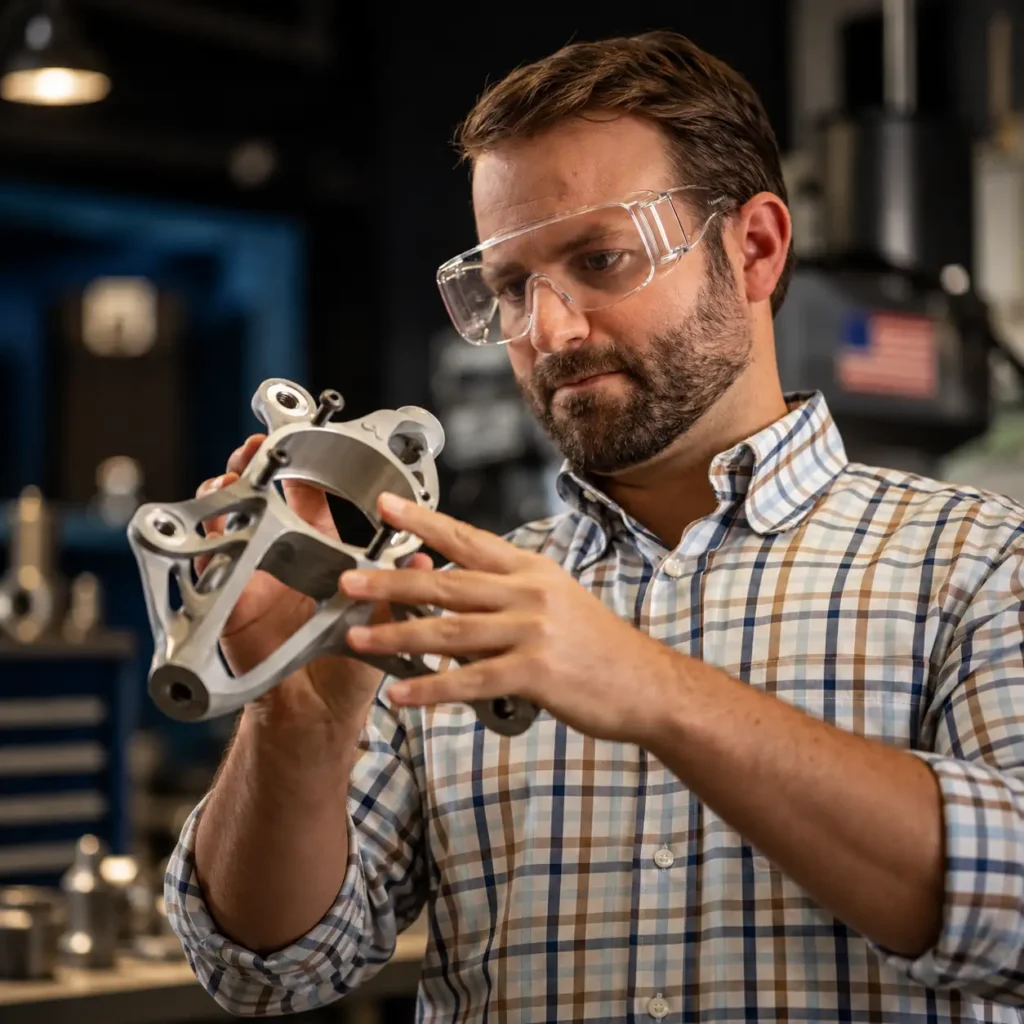
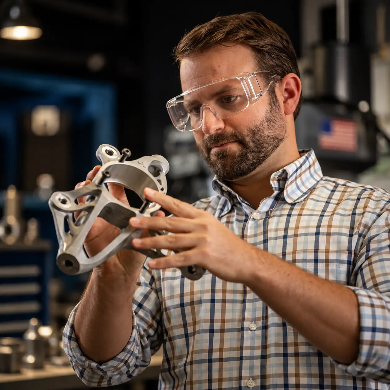
Topology optimization is one of the most widely discussed applications of design for additive manufacturing.
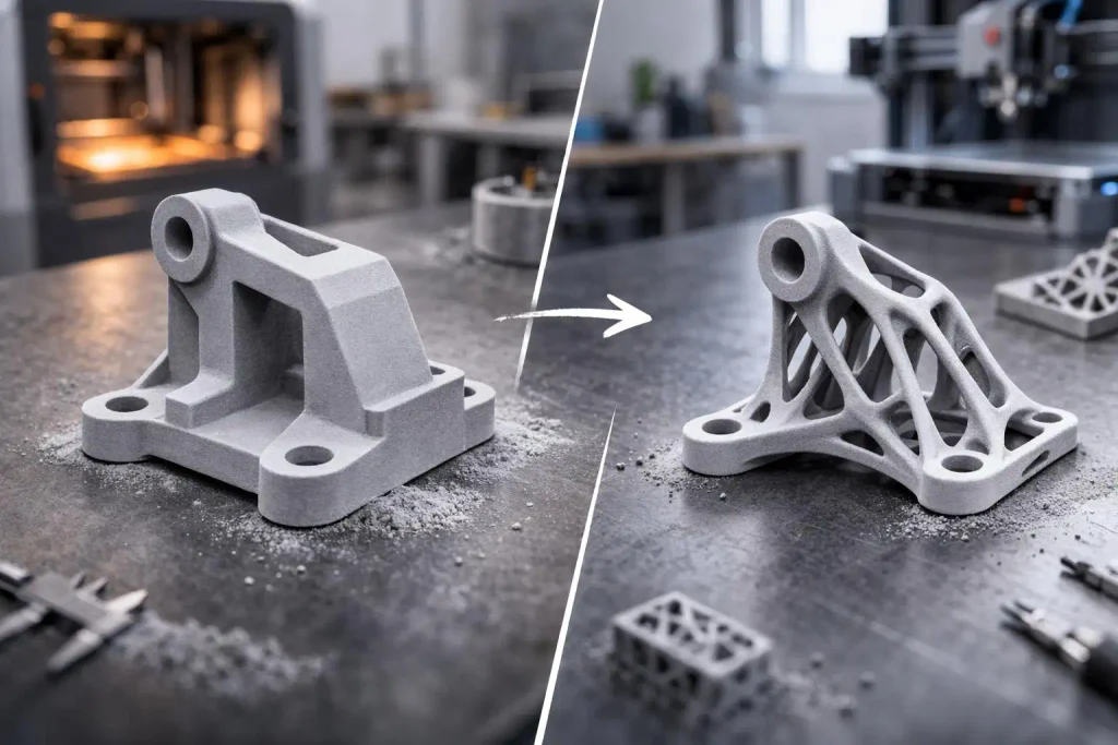
The process uses defined loads, constraints, material properties and optimization objectives to identify how material can be distributed within a permitted design space.
Instead of beginning with a conventional solid geometry, engineers can investigate alternative structures that place material where it contributes to the required performance.
For industrial components, topology optimization may support weight reduction, stiffness improvement or more efficient load paths.
<AsyncImage query=”engineering topology optimized metal bracket next to conventional solid metal bracket industrial engineering workshop” aspectRatio=”16:9″ width=”100%”/>
The resulting geometries may contain branching structures, organic transitions or internal features that are difficult to produce using conventional machining.
However, the output of a topology optimization study is not necessarily a manufacturing-ready design.
Engineers still need to evaluate stress concentrations, fatigue behaviour, minimum feature sizes, support requirements, build orientation and finishing operations.
Topology optimization is therefore most useful when integrated into a broader engineering and manufacturing workflow.
Finite Element Analysis and Structural Validation
Finite element analysis (FEA) can help engineers evaluate how a proposed component responds to defined loading and boundary conditions.
For metal additive manufacturing, FEA may be used to investigate stress distribution, displacement, stiffness, thermal loading and other relevant structural responses.
It can also support comparisons between an existing component and a redesigned alternative.
For example, an engineer may use FEA to evaluate whether a lighter component maintains acceptable stiffness under its expected operating loads.
However, simulation results depend on the quality of the input assumptions, material data, mesh, loading conditions and boundary constraints.
Where fatigue, fracture, safety-critical operation or demanding service environments are involved, additional analysis and physical validation may be required.
DfAM should therefore connect simulation with manufacturing and inspection rather than treating computational results as sufficient proof of component performance.
Build Orientation and Its Effect on Component Design
Build orientation is a critical consideration in many metal additive manufacturing processes, particularly laser powder bed fusion.
The orientation of a component within the build volume can influence support requirements, surface finish, dimensional accuracy, build height and thermal behaviour.
It can also affect the direction of layer formation relative to the component’s loading conditions.
A geometry that appears efficient in CAD may become expensive or difficult to manufacture if it requires extensive support structures or creates inaccessible surfaces.
Engineers should therefore evaluate build orientation early in the design process.
The objective is to find an appropriate balance between component performance, manufacturing feasibility, post-processing and production efficiency.
Build orientation is not simply a decision made by the machine operator after the design is complete. It can influence the geometry of the component itself.
Support Structures and Overhang Design
In processes such as laser powder bed fusion, support structures can serve several functions.
They may help anchor the component, conduct heat into the build plate and support geometries that cannot otherwise be produced reliably.
However, supports also consume material and machine time, and their removal can introduce additional labour or machining requirements.
Support structures placed inside narrow channels or inaccessible cavities may be particularly problematic.
DfAM can reduce these challenges by modifying overhang angles, changing feature orientation, redesigning internal passages or dividing a component where necessary.
The goal is not always to eliminate every support.
It is to design the component so that required supports can be produced and removed without compromising its function or creating unnecessary manufacturing complexity.
Designing Internal Channels and Complex Flow Paths
Metal additive manufacturing can enable internal geometries that are difficult or impossible to create using conventional machining.
This capability is relevant to heat exchangers, fluid-handling components, cooling systems and other industrial applications where internal geometry influences performance.
Engineers may be able to develop curved channels, integrated manifolds or more compact flow paths.
However, internal features introduce additional design considerations.
Powder removal, surface roughness, minimum channel dimensions, inspection access and post-processing feasibility must all be evaluated.
For fluid-handling components, computational fluid dynamics may help investigate pressure loss, flow distribution and other relevant performance characteristics.
A complex internal channel should be selected because it serves an engineering purpose, not simply because additive manufacturing makes it geometrically possible.
Part Consolidation: Reducing Assembly Complexity
Part consolidation involves redesigning multiple components as a smaller number of integrated parts.
Metal additive manufacturing can make this possible when conventional manufacturing requires separate pieces because of tooling access, joining or geometric limitations.
For suitable applications, consolidation may reduce the number of fasteners, joints, assembly operations or potential leakage interfaces.
It can also create opportunities to integrate features that previously required separate manufacturing steps.
However, consolidation can introduce trade-offs.
A single integrated component may be more difficult to inspect, repair or replace. A failure in one region may require replacement of the entire part rather than a smaller subcomponent.
Engineers should therefore evaluate the complete product lifecycle before consolidating an assembly.
The most appropriate design is not necessarily the one with the fewest parts.
It is the one that provides the required performance, manufacturability and maintainability.
Lattice Structures and Lightweight Design
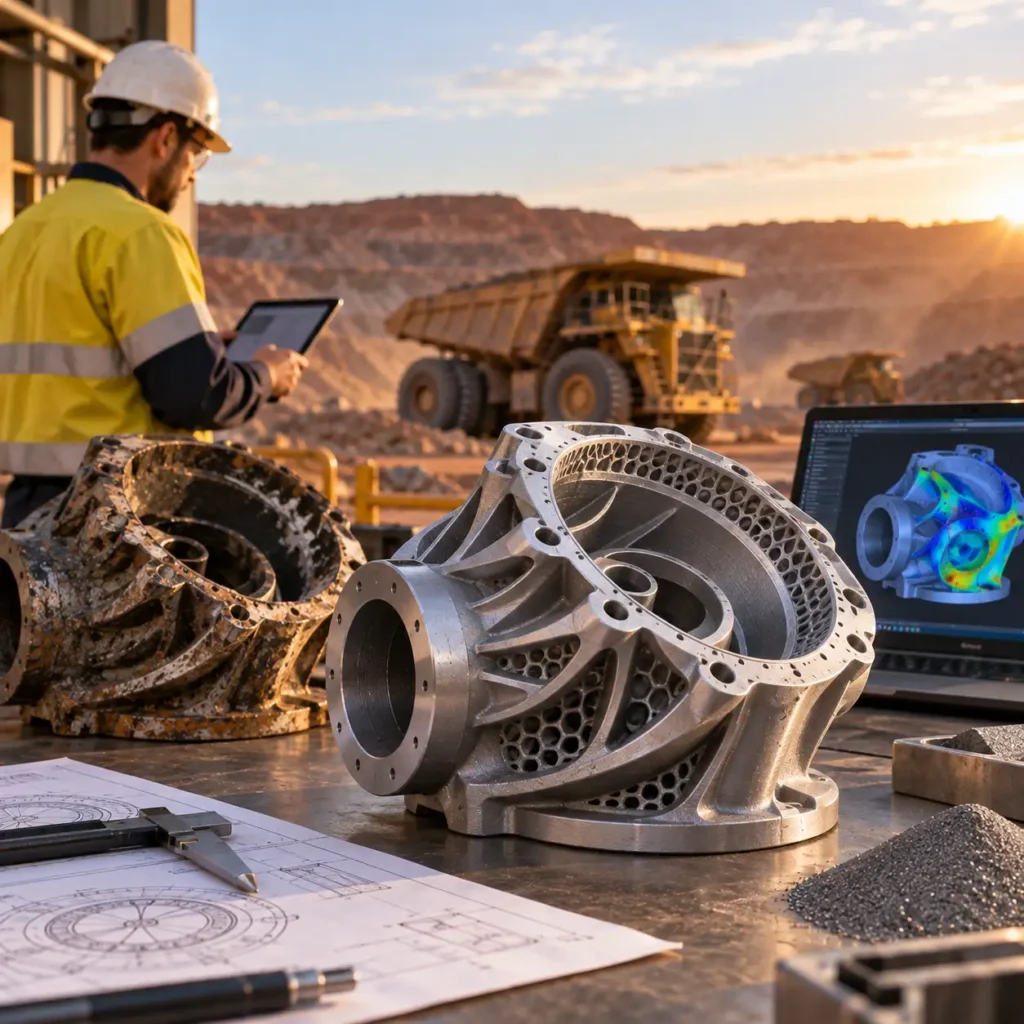
Lattice structures can provide another approach to controlling material distribution in metal additive manufacturing.
Instead of using a completely solid internal volume, engineers can investigate cellular geometries that may offer useful combinations of weight, stiffness, energy absorption or thermal behaviour.
Lattice structures may be relevant to selected lightweight components, tooling and specialised industrial applications.
Their suitability depends on cell geometry, loading conditions, manufacturing resolution, material behaviour and the ability to remove powder from internal regions.
The design must also account for how the lattice connects to surrounding solid material.
For industrial components, lattice structures should be evaluated against functional requirements and validated appropriately rather than introduced solely for weight reduction.
Material Selection for Metal Additive Manufacturing
Material selection should be considered alongside geometry from the beginning of the DfAM process.
The appropriate material depends on the component’s operating environment, loading conditions, corrosion exposure, temperature requirements and other application-specific factors.
Commonly used metal additive manufacturing material families include stainless steels, aluminium alloys, titanium alloys and nickel-based alloys, although availability depends on the selected manufacturing process and equipment.
The same alloy designation does not necessarily guarantee identical properties across different manufacturing routes.
Mechanical behaviour can be influenced by processing conditions, build orientation, heat treatment, porosity, surface condition and other variables.
For demanding industrial applications, material selection should therefore include consideration of the required properties in the final manufactured condition.
Tolerances, Surface Finish and Post-Processing
A successful DfAM project must account for the difference between a printed component and a finished component.
Metal additive manufacturing may produce a near-net-shape part, but critical surfaces and interfaces can still require secondary operations.
These may include machining, heat treatment, support removal, surface finishing and inspection.
For example, a printed housing may require machining of bearing seats, sealing surfaces or mounting interfaces.
A component with demanding fatigue requirements may also need particular attention to surface condition and post-processing.
Engineers should identify these requirements during the design stage so that sufficient material allowance and suitable access are provided.
Designing for post-processing is therefore an essential part of designing for additive manufacturing.
Design for Inspection and Quality Assurance
Inspection requirements can influence component geometry just as manufacturing requirements do.
Complex internal structures, enclosed channels and integrated assemblies may be difficult to inspect using conventional measurement methods.
Where appropriate, dimensional inspection, 3D scanning, coordinate measurement or other inspection techniques can help evaluate the manufactured component against its design requirements.
The selected inspection method should be appropriate for the feature being assessed.
External scanning, for example, does not establish the geometry or integrity of inaccessible internal features.
DfAM should therefore consider how critical characteristics will be verified before the component is manufactured.
Design for Additive Manufacturing in Australian Mining
Australian mining operations often rely on specialised components operating under demanding mechanical and environmental conditions.
These may include wear, vibration, impact, corrosion and complex loading.
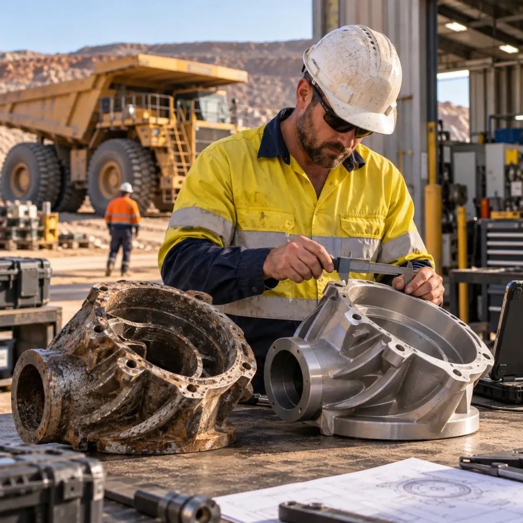
For selected mining applications, DfAM can provide opportunities to investigate redesigned brackets, housings, fluid-handling components, specialised tooling and other low-volume industrial parts.
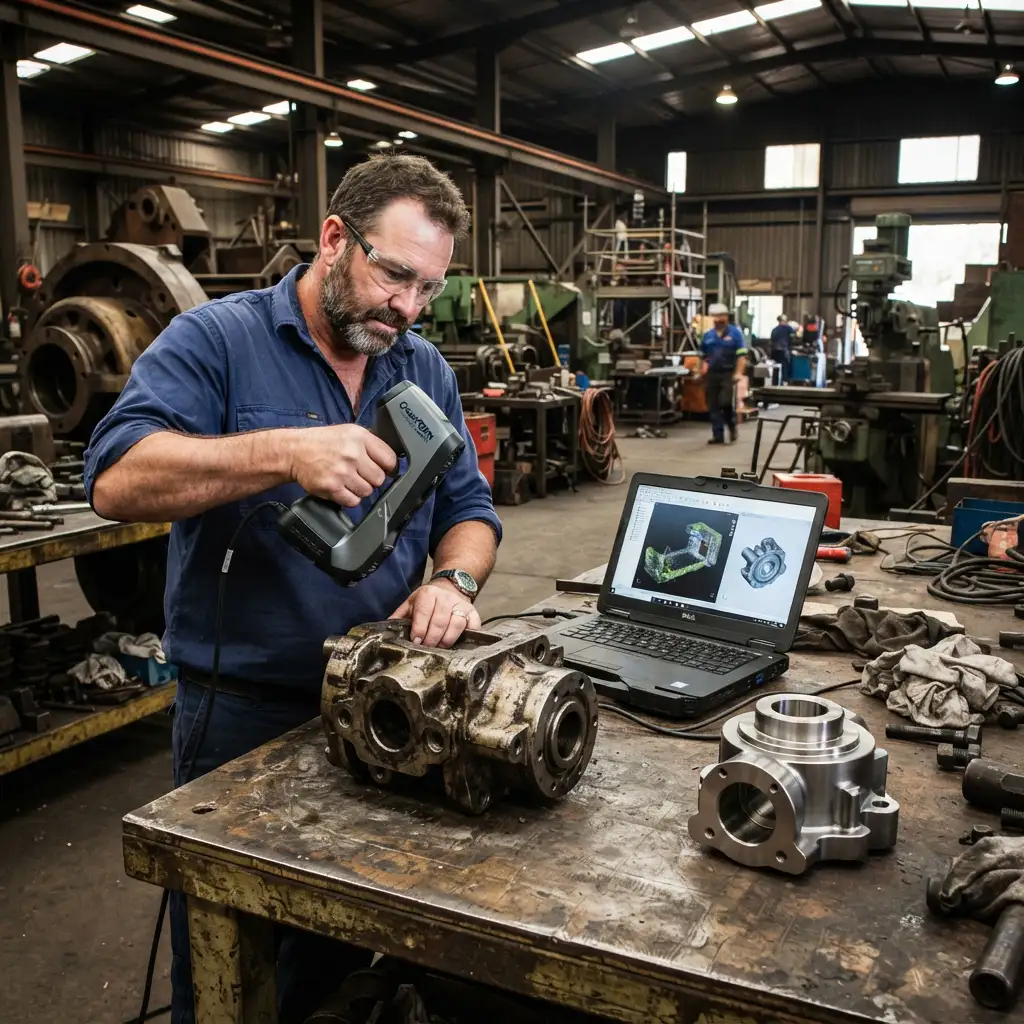
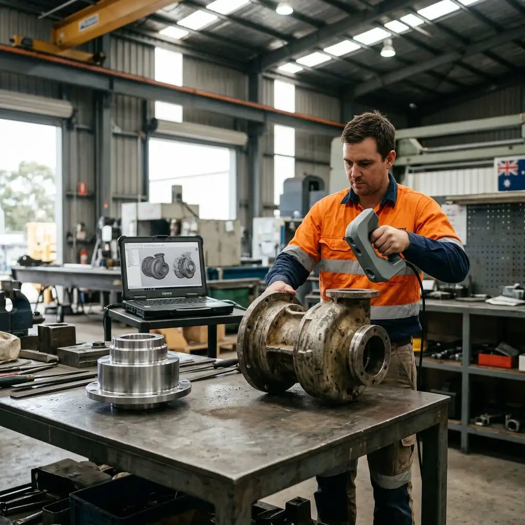
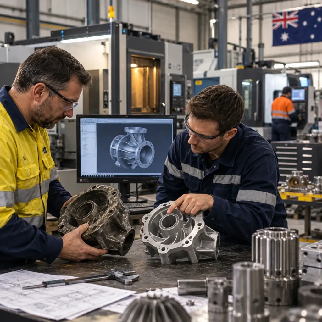
An existing component can be scanned and reconstructed in CAD before being evaluated for additive manufacturing.
The engineering team can then investigate whether the geometry should be reproduced, optimized or redesigned for a different manufacturing approach.
This creates a direct connection between reverse engineering, design optimization and metal additive manufacturing.
The suitability of the final component must still be assessed against its operating requirements, material specifications, inspection needs and economic constraints.
Combining Reverse Engineering with DfAM
Reverse engineering and DfAM address different stages of the same engineering challenge.
Reverse engineering recovers usable design information from an existing physical component.
DfAM evaluates how that design should be adapted for additive manufacturing.
The combined workflow may follow this sequence:
Physical component → 3D scanning → CAD reconstruction → engineering assessment → DfAM → metal additive manufacturing → post-processing and inspection
This approach is particularly relevant when a company needs to replace an obsolete component but is not restricted to reproducing its original manufacturing method.
Instead of copying every feature of the existing part, engineers can preserve critical functional interfaces while reconsidering non-essential geometry.
This may create opportunities to reduce weight, consolidate parts or improve manufacturing efficiency where the engineering requirements permit.
When Does DfAM Make Economic Sense?
Design for additive manufacturing should consider the complete manufacturing and lifecycle cost of the component.
Metal 3D printing is not automatically the most economical production method.
For simple geometries produced in large quantities, conventional manufacturing may remain more appropriate.
DfAM can become particularly relevant when a component has one or more of the following characteristics:
- Complex geometry
- Low production volume
- High conventional tooling costs
- Significant assembly complexity
- Opportunities for functional integration
- Weight-sensitive performance requirements
- Specialised or obsolete component requirements
- Difficult conventional manufacturing constraints
The economic assessment should include engineering effort, material use, build time, supports, post-processing, inspection and qualification where required.
The strongest applications are those where additive manufacturing provides a measurable engineering or operational benefit rather than merely an alternative way to produce the same geometry.
A Practical DfAM Workflow for Industrial Components
A structured DfAM project connects engineering requirements with the selected manufacturing process.
The process begins by establishing the component’s function, material requirements, loading conditions, interfaces and quality expectations.
Engineers then assess whether metal additive manufacturing is technically and economically appropriate.
Where a physical component already exists, industrial 3D scanning and reverse engineering may provide the initial CAD model.
The design can then be evaluated through geometric optimization, simulation and manufacturing feasibility assessment.
Build orientation, support structures, internal features and post-processing requirements should be considered before the final geometry is approved.
Manufacturing and inspection provide the evidence needed to evaluate whether the finished component meets its defined requirements.
This integrated approach helps reduce the risk of developing a design that is attractive in CAD but impractical to manufacture or unsuitable for its intended application.
Conclusion
Design for metal additive manufacturing connects component engineering with the capabilities and constraints of metal 3D printing.
It allows engineers to reconsider conventional geometries, investigate topology optimization, consolidate assemblies and develop complex features while accounting for material behaviour, build orientation, support requirements and post-processing.
For Australian mining, manufacturing and industrial engineering applications, DfAM can provide a practical pathway from an existing component or initial CAD model to a design developed specifically for additive manufacturing.
The greatest value comes from treating design, analysis, manufacturing and inspection as connected engineering activities rather than independent stages.
E-Metal3D supports this approach through industrial 3D scanning, reverse engineering, engineering solutions and metal additive manufacturing, helping Australian companies evaluate and develop industrial components for appropriate manufacturing applications.
What is design for metal additive manufacturing?
Design for metal additive manufacturing, or DfAM, is the process of developing or adapting components for metal 3D printing while considering structural performance, geometry, materials, build orientation, supports and post-processing.
What is the difference between DfAM and conventional design?
Conventional design often accounts for machining access, tooling, moulding or assembly limitations. DfAM considers the capabilities and constraints of additive manufacturing, including layer-based production, complex geometries, support structures and thermal behaviour.
Is topology optimization necessary for metal 3D printing?
No. Topology optimization is one possible DfAM technique. Many successful metal additive manufacturing components do not require it. Its suitability depends on the component’s engineering requirements and optimization objectives.
Can an existing component be redesigned for metal 3D printing?
Yes. An existing component can be reconstructed from drawings or through reverse engineering and then evaluated for additive manufacturing. Critical dimensions, interfaces and performance requirements must be preserved or appropriately validated.
Does metal additive manufacturing eliminate machining?
Not necessarily. Critical interfaces, precision bores, sealing surfaces and other features may still require machining or additional finishing after printing.
How does build orientation affect metal 3D printing?
Build orientation can influence support requirements, surface finish, dimensional accuracy, build time and material behaviour. The effects depend on the selected additive manufacturing process and component geometry.
Can DfAM improve mining components?
DfAM may provide opportunities to redesign suitable mining components through weight reduction, part consolidation or improved geometry. The resulting design must still meet the component’s operating, material and quality requirements.
Is metal additive manufacturing suitable for every industrial component?
No. Suitability depends on geometry, material, quantity, mechanical requirements, cost, inspection and manufacturing constraints. Conventional manufacturing may remain more appropriate for many applications.