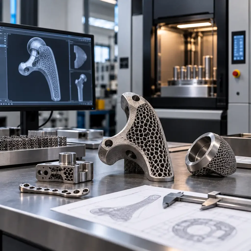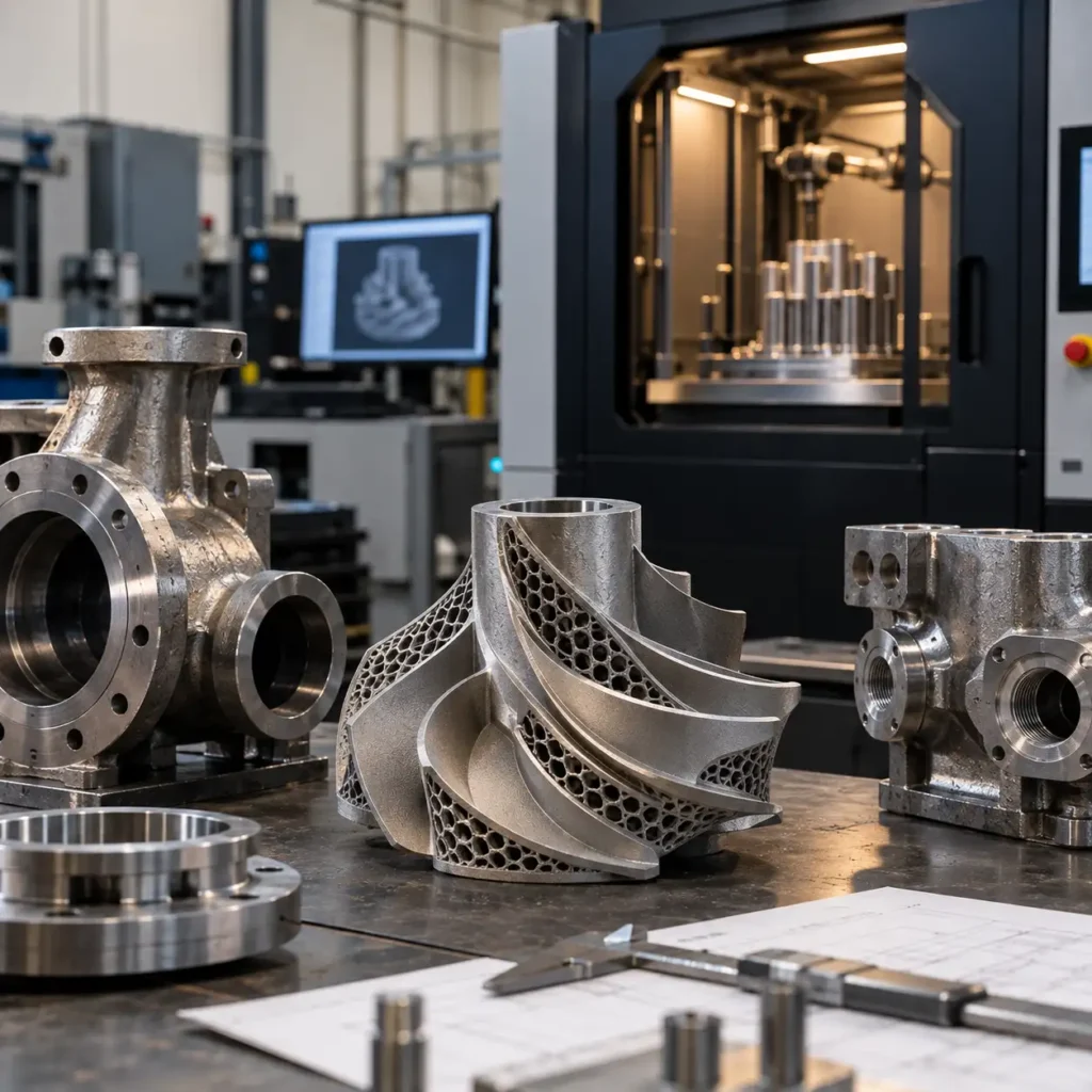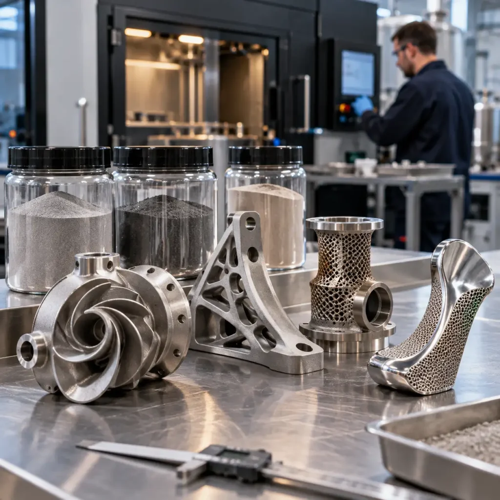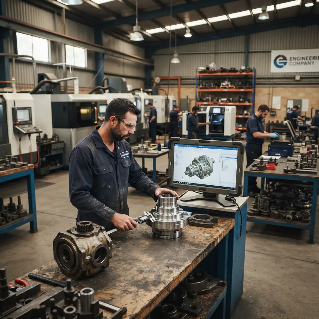
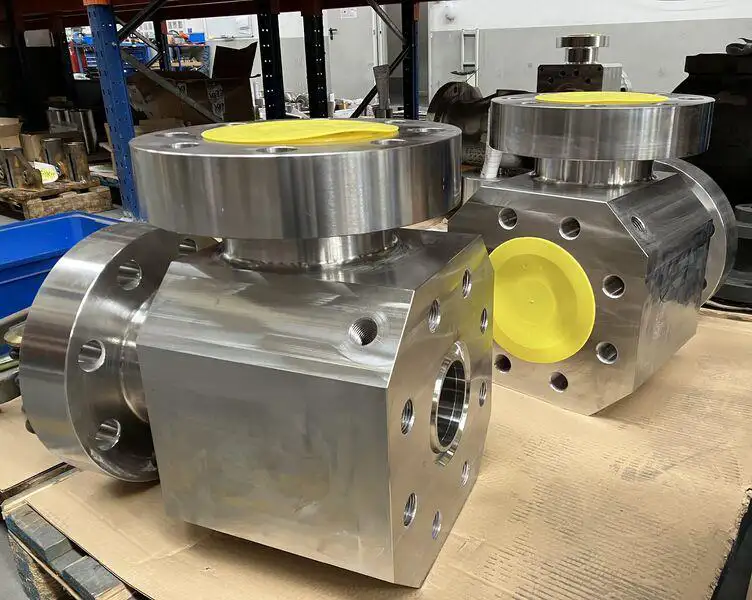
Metal additive manufacturing for oil and gas applications is creating new opportunities to design and produce complex pump components, valve-related parts and internal flow passages. Using technologies such as Laser Powder Bed Fusion (LPBF), engineers can investigate geometries that are difficult to manufacture conventionally while addressing critical requirements for material performance, dimensional accuracy, surface finishing and component qualification.
For these applications, metal additive manufacturing offers more than an alternative way to produce a metal part. It allows engineers to reconsider how internal passages are arranged, how multiple components are integrated and how specialised geometries can be manufactured.
However, design freedom does not automatically translate into a better or qualified component. A successful application requires careful assessment of fluid performance, mechanical integrity, material behaviour, surface finish, inspection accessibility and the relevant service requirements.
This article examines where Laser Powder Bed Fusion (LPBF) can add value to oil and gas pumps, valves and flow components, and how engineering teams can determine whether additive manufacturing is an appropriate production route.
Why Pumps, Valves and Flow Components Are Important Candidates for Additive Manufacturing
Many components in fluid-handling equipment are defined by two competing requirements: they must provide an effective flow path while maintaining sufficient structural integrity.
Traditional manufacturing methods, including casting, machining, drilling and fabrication, are well established for these applications. They are often economical, repeatable and supported by extensive qualification experience.
Their limitations become more apparent when a component requires complex intersecting passages, compact internal manifolds, difficult-to-access cavities or several separately manufactured parts.
Metal additive manufacturing can provide an alternative where conventional production imposes significant geometric constraints.
Potential applications include:
- Pump impellers and selected hydraulic components.
- Valve bodies with complex internal passages.
- Flow distribution manifolds and fluid connectors.
- Specialised nozzles and mixing components.
- Compact heat-transfer and fluid-handling assemblies.
- Engineering prototypes used to investigate alternative flow geometries.
Not every component in these categories is suitable for LPBF. Large, relatively simple housings may remain more economical to cast or machine. Safety-critical pressure-retaining parts also introduce qualification requirements that can outweigh the manufacturing benefits.
The engineering opportunity is therefore not to replace conventional production indiscriminately, but to identify components where geometric flexibility produces a measurable advantage.
Metal Additive Manufacturing for Pump Components
Pump performance depends on the interaction between impeller geometry, fluid properties, rotational speed, operating conditions and the surrounding hydraulic system.
In suitable designs, LPBF can enable impeller geometries that would be difficult to manufacture through conventional subtractive methods.
Impellers and complex hydraulic geometries
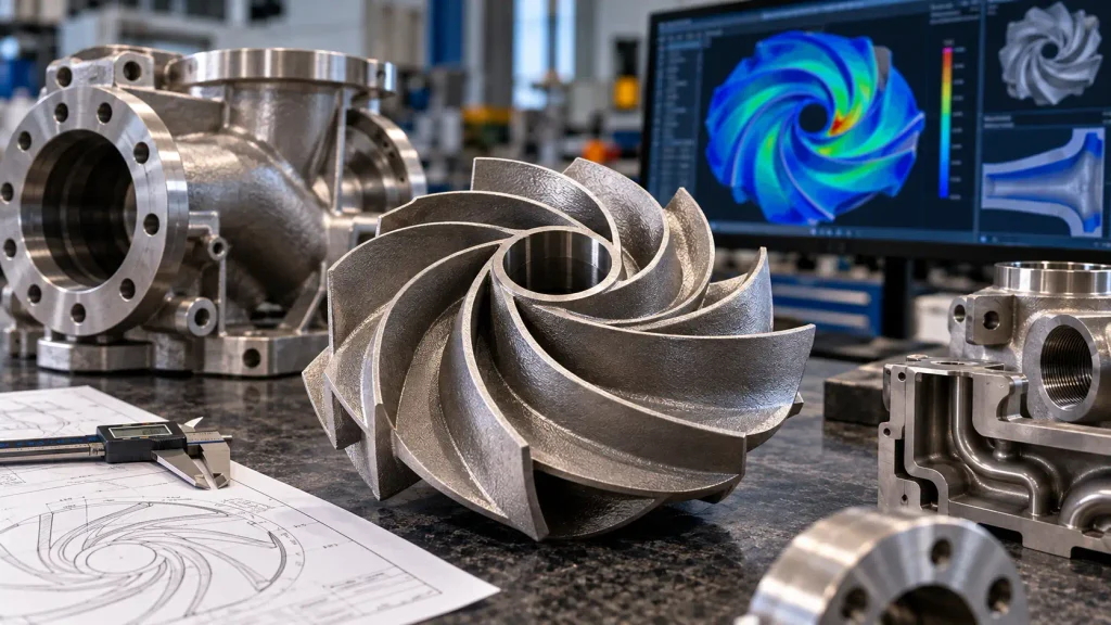
An impeller contains flow passages formed by the relationship between its blades, hub and surrounding surfaces. Depending on the pump configuration, these features may include curved channels, narrow passages or partially enclosed geometries.
Additive manufacturing can make certain geometries accessible without the tooling or assembly steps otherwise required.
Potential design opportunities include modified blade profiles, integrated features and geometries developed through computational fluid dynamics (CFD).
However, a printable impeller is not necessarily a functional impeller.
The design must still address hydraulic efficiency, cavitation behaviour, mechanical loading, rotational balance and operating speed. Surface condition is especially important because as-built LPBF surfaces may be considerably rougher than conventionally machined hydraulic surfaces.
Where performance depends on smooth flow passages, additional finishing or design changes may be necessary.
Structural and operational considerations
Rotating pump components require particular attention to fatigue, dynamic balance, dimensional tolerances and defect sensitivity.
Build orientation, support removal, heat treatment, machining allowances and inspection methods should be considered before manufacturing begins.
For a rotating component, dimensional conformity alone is insufficient to establish suitability for operation. Material properties, dynamic behaviour and application-specific testing must also be evaluated.
A practical engineering assessment should compare the proposed additively manufactured design against an established baseline rather than assuming that greater geometric complexity will improve performance.
Additive Manufacturing for Valve Bodies and Flow Control Components
Valve bodies combine structural requirements with fluid control functions. Their internal geometry can include intersecting bores, cavities, changes in flow direction and connections to surrounding equipment.
Traditional valve production is highly mature, particularly for standardised designs. Conventional casting, forging and machining will often remain the preferred manufacturing routes.
LPBF becomes more interesting when a valve-related component requires unusual geometry, compact packaging, integrated passages or low-volume production.
Redesigning internal flow passages
Additive manufacturing can allow engineers to investigate smoother transitions between passages or reduce the number of abrupt internal intersections.
In principle, this may help manage local flow separation or pressure losses in specific designs.
The actual outcome depends on the fluid, flow regime, operating conditions and manufactured surface quality. CFD can help compare design alternatives, but simulation results must be interpreted alongside material and manufacturing constraints.
For some applications, a redesigned flow passage may offer no meaningful improvement over a conventionally manufactured component.
Pressure-retaining boundaries and sealing surfaces
A valve body intended to contain pressure presents requirements beyond geometric accuracy.
The design and manufacturing process may need to demonstrate adequate mechanical properties, material traceability, defect control, pressure integrity and compatibility with the intended service.
Sealing surfaces, threaded connections, flange faces and precision bores will often require post-build machining.
Internal porosity, lack-of-fusion defects or surface-connected discontinuities can be particularly important where leakage or fatigue is a concern.
Consequently, pressure-retaining valve components should not be treated as automatically suitable for service simply because they can be printed.
Their acceptance must follow the applicable engineering specifications, qualification requirements and inspection procedures.
Complex Manifolds and Internal Flow Channels
One of the clearest geometric opportunities for LPBF lies in compact manifolds.
A conventionally manufactured manifold may require multiple drilled passages, cross-drilling, plugs, fittings or assembled components to create a particular flow distribution network.
With additive manufacturing, the passage layout can be designed more directly around the required fluid connections, subject to manufacturing constraints.
This creates opportunities for component consolidation and more compact packaging.
Potential benefits of integrated manifold designs
A well-designed additively manufactured manifold may reduce the number of separate components, external connections or assembly operations.
Fewer interfaces can simplify assembly and may reduce some potential leakage paths. However, this benefit depends on the original design and does not remove the need for pressure integrity testing.
Integrated passages can also introduce new difficulties.
Internal surfaces may be inaccessible to conventional machining. Residual powder can become trapped in enclosed channels, and supports may be impossible to remove from certain cavities.
The design must therefore consider not only whether a passage can be printed, but also whether it can be cleaned, inspected and verified.
The hidden challenge of internal passages
A flow channel that looks satisfactory in CAD may be unsuitable for production if it contains unsupported downward-facing surfaces, inaccessible cavities or geometry that prevents complete powder removal.
Channel orientation, cross-sectional shape, minimum feature size and access openings should be considered during Design for Additive Manufacturing (DfAM).
For some applications, non-circular or self-supporting channel profiles can reduce the need for internal support structures.
Such changes must still be assessed for their effect on flow performance and pressure losses.
A useful design rule is that every internal passage should have a credible manufacturing, cleaning and verification strategy before the geometry is finalised.
Design for Additive Manufacturing: Balancing Flow and Structural Performance
The most valuable LPBF designs are rarely direct copies of conventional components.
Instead, engineers should evaluate whether the component can be redesigned to use additive manufacturing effectively while preserving the requirements that determine safe operation.
For pumps, valves and manifolds, this involves several interconnected disciplines.
Fluid dynamics and flow behaviour
CFD can support the investigation of pressure distribution, velocity fields, recirculation and potential areas of excessive flow resistance.
However, CFD results depend on the boundary conditions, turbulence model, mesh quality and assumptions about the manufactured geometry.
As-built surface roughness may affect the flow differently from the idealised smooth-wall CAD model.
Where internal passages cannot be finished to the assumed surface condition, the simulation should account for the expected manufacturing outcome.
Structural analysis and mechanical integrity
Finite Element Analysis (FEA) can support assessment of stress concentrations, deformation and loading under defined operating conditions.
For pressure-containing or cyclically loaded components, analysis may need to consider pressure fluctuations, thermal expansion, vibration and fatigue.
Additive manufacturing also introduces process-related considerations, including residual stress, anisotropy and defect sensitivity.
Simulation should therefore use material properties and assumptions appropriate to the selected process and qualification state.
Manufacturing constraints
A design that performs well in CFD and FEA may still be difficult to manufacture reliably.
LPBF imposes practical constraints involving build volume, orientation, supports, thermal distortion, recoating, powder evacuation and subsequent machining.
Engineering teams should assess these constraints early, rather than waiting until the design has already been optimised for fluid performance.
Material Selection for Oil and Gas Applications
Material selection should begin with the actual service environment, not with the list of alloys available for a metal 3D printer.
Oil and gas components may encounter chloride-bearing fluids, elevated temperatures, erosive particles, pressure cycling and chemically aggressive environments.
The suitability of a material depends on its composition, microstructure, manufacturing condition, post-processing and the applicable equipment requirements.
Stainless steel alloys
316L stainless steel is commonly considered for corrosion-resistant industrial components and is available for many LPBF systems.
Its suitability depends on the fluid chemistry, temperature, mechanical loading and corrosion mechanisms involved.
316L should not be assumed suitable for every chloride-rich or sour-service environment.
Nickel-based alloys
Nickel-based alloys such as Inconel 625 and 718 are relevant to demanding engineering applications, although their strengths and corrosion characteristics differ.
Alloy selection must account for the intended operating conditions and the properties achieved through the specific additive manufacturing and heat-treatment route.
An alloy’s conventional manufacturing reputation does not automatically establish the performance of an LPBF component.
Material qualification matters more than alloy names
Powder chemistry, reuse practices, process parameters, build orientation, heat treatment and inspection can all influence final properties.
For demanding applications, material acceptance may require testing of representative specimens, traceability records and evidence that the manufacturing route consistently produces the required characteristics.
In sour-service environments, applicable material restrictions and standards must be assessed separately. A material’s availability for printing is not evidence of compliance with those requirements.
Post-Processing and Surface Finishing Requirements
LPBF is often only one stage of the manufacturing process.
Depending on the component, post-processing may include stress relief, heat treatment, removal from the build plate, support removal, machining, surface finishing and cleaning.
For pumps and flow components, surface finishing can be particularly important.
Hydraulic surfaces may require improved roughness to achieve the intended flow characteristics. Sealing interfaces, bearing seats, threads and precision connections generally require controlled finishing operations.
Internal channels are more challenging because conventional tools may not reach them.
Potential finishing approaches must be evaluated against channel accessibility, material, geometry and required surface condition.
Importantly, no finishing method should be assumed capable of producing a uniform result throughout every complex internal passage.
Design decisions should account for the available post-processing methods before the part is printed.
Inspection and Qualification of Additively Manufactured Oil and Gas Components
Inspection and qualification are central to the use of metal additive manufacturing in demanding energy applications.
The required evidence depends on the component’s function, criticality, service environment and applicable contractual or regulatory requirements.
Dimensional inspection
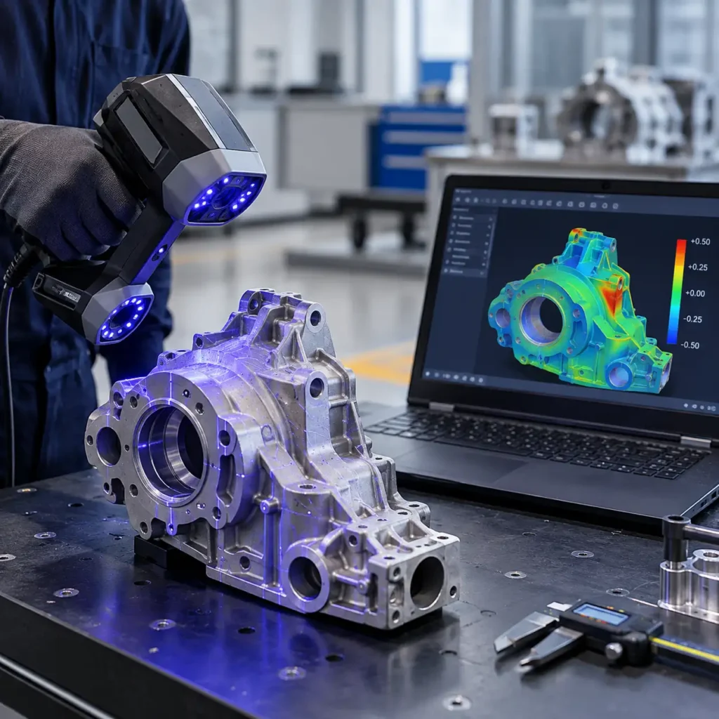
Dimensional verification may use coordinate measurement, optical 3D scanning or other appropriate metrology methods.
External scan-to-CAD comparison can help identify geometric deviations, but it cannot by itself establish the integrity of enclosed channels or internal material.
Non-destructive testing
Depending on the component, inspection may involve suitable non-destructive testing methods to investigate discontinuities or internal defects.
Industrial computed tomography can provide information about certain internal features, but its suitability depends on component size, material, geometry, resolution and acceptance criteria.
No single inspection method is appropriate for every LPBF component.
Pressure and functional testing
For relevant flow-handling components, testing may include pressure integrity, leakage, hydraulic performance or other application-specific assessments.
Rotating components can require additional mechanical and dynamic evaluation.
The testing programme should be defined from the service requirements and failure consequences, not simply from the fact that the component was additively manufactured.
Relevant industry standards
Two important references for engineering teams are API Standard 20S, addressing qualification and production control for metallic additive manufacturing in petroleum and natural gas applications, and DNV-ST-B203, providing a framework for additive manufacturing quality and qualification.
These standards help structure decisions around manufacturing processes, documentation, inspection and part acceptance.
Their relevance and applicability must be established for the specific component and project. Referencing a standard does not mean that a supplier or part is certified to it.
When Is Metal Additive Manufacturing the Right Choice?
LPBF should be evaluated against the most appropriate conventional manufacturing alternative.
The following comparison provides an initial screening framework.
| Engineering consideration | LPBF may be attractive when… | Conventional manufacturing may be preferable when… |
|---|---|---|
| Internal geometry | Complex passages are difficult to machine or assemble | Geometry is simple and accessible |
| Production volume | Low-volume, specialised parts are required | High-volume production benefits from established tooling |
| Component integration | Multiple parts can be consolidated | Separate components are easier to inspect or maintain |
| Material utilisation | Conventional machining would remove substantial material | Material use is already efficient |
| Surface requirements | Required surfaces can be finished and verified | Extensive inaccessible finishing would be necessary |
| Qualification | A suitable qualification pathway can be established | An established qualified process is already available |
| Component size | The part fits the available build envelope | The part exceeds practical LPBF dimensions |
A more complete decision should include total delivered cost, inspection requirements, manufacturing lead time, expected production volume and lifecycle considerations.
The shortest print time is not necessarily the shortest qualified delivery time.
For critical components, testing and approval activities may represent a substantial part of the overall schedule.
A Practical Engineering Workflow for Pumps, Valves and Flow Components
A structured assessment can help avoid investing in an additive design that cannot be manufactured or qualified.
Step 1: Define the operating requirements
Document the component’s function, pressure and temperature conditions, fluid properties, loading, dimensional requirements and expected service life.
Identify relevant industry specifications and any restrictions on materials or manufacturing routes.
Step 2: Establish the manufacturing baseline
Review how the existing component is manufactured and why an alternative process is being considered.
Determine whether the opportunity relates to geometry, availability, assembly complexity, material use or production volume.
Step 3: Evaluate additive manufacturing feasibility
Assess build size, material availability, orientation, support strategy, powder removal, finishing and inspection accessibility.
Eliminate geometries that cannot be cleaned or verified adequately.
Step 4: Develop and assess the design
Use CAD, CFD and FEA where appropriate to evaluate proposed changes.
Compare performance against the baseline design and consider manufacturing variability.
Step 5: Plan manufacturing and post-processing
Define the build approach, machining allowances, heat treatment, surface finishing and dimensional verification requirements.
Step 6: Establish qualification and acceptance criteria
Determine the evidence needed to demonstrate conformity with the applicable requirements.
This may involve material testing, non-destructive examination, pressure testing, functional testing and documented traceability.
Step 7: Compare the complete production route
Assess additive manufacturing against casting, machining or fabrication based on total cost, lead time, technical risk and qualification effort.
Only then should the preferred production method be selected.
Supporting Oil and Gas Engineering in Australia
Australian oil and gas operations require manufacturing solutions that account for equipment reliability, specialised component requirements and the practical challenges of industrial supply chains.
For suitable applications, metal additive manufacturing can support engineering development, low-volume production and the investigation of alternative component geometries.
E-Metal3D supports Australian industrial customers through Metal 3D Printing, Engineering Solutions and 3D Scanning Services.
These capabilities can contribute to workflows involving component assessment, reverse engineering, design development and additive manufacturing feasibility.
For a broader overview of applications across the energy sector, explore E-Metal3D’s Oil and Gas industry solutions.
Component suitability, inspection requirements and qualification responsibilities should always be established for the individual project.
Conclusion
Metal additive manufacturing offers meaningful opportunities for selected oil and gas pump components, valve-related parts and complex flow-handling assemblies.
Its greatest potential often lies in geometries that are difficult to manufacture conventionally, including integrated manifolds and specialised internal passages.
However, successful implementation requires more than the ability to print a complex shape. Fluid performance, structural integrity, material behaviour, surface finish, inspection accessibility and qualification must all be considered together.
For Australian engineering teams, the most effective approach is to evaluate LPBF as one manufacturing option within a broader technical and commercial decision.
Discuss a component with E-Metal3D
If your team is assessing a pump, valve-related component or complex industrial flow geometry for additive manufacturing, contact E-Metal3D to discuss the design requirements and available engineering and manufacturing pathways.
Can metal 3D printing be used to manufacture oil and gas pump impellers?
Yes, selected pump impeller designs can be manufactured using metal additive manufacturing. Suitability depends on geometry, material properties, surface finishing, balance, fatigue performance and the required qualification and testing programme.
Are 3D printed valve bodies suitable for high-pressure applications?
Some additively manufactured valve components may be suitable for pressure-related applications when the design, material, manufacturing process, inspection and testing satisfy the applicable requirements. Printability alone does not establish pressure integrity or service approval.
What is the advantage of LPBF for internal flow channels?
LPBF can manufacture certain complex internal passages without conventional drilling or assembly operations. This may support more compact designs or integrated manifolds, provided the channels can be manufactured, cleaned, inspected and verified.
Which materials are suitable for oil and gas additive manufacturing?
Materials such as 316L stainless steel and selected nickel-based alloys may be considered, depending on the service environment and qualified manufacturing route. Corrosion, temperature, loading and applicable material standards determine suitability.
Can CFD predict the performance of a 3D printed flow component?
CFD can help compare design alternatives and investigate flow behaviour. Its predictions depend on modelling assumptions and should account for the manufactured geometry and surface condition. Physical testing may still be required.
Does additive manufacturing eliminate the need for machining?
Usually not. Critical sealing surfaces, precision bores, threads and connection features may require machining or other finishing operations after printing.
How are additively manufactured oil and gas components inspected?
Inspection may involve dimensional metrology, material testing, non-destructive examination, pressure testing and functional assessment, depending on the component’s requirements and criticality.
Which standards are relevant to metal additive manufacturing in oil and gas?
API Standard 20S and DNV-ST-B203 provide relevant frameworks for metallic additive manufacturing qualification and quality management. Their applicability must be determined for each project; referencing them does not establish certification or approval.