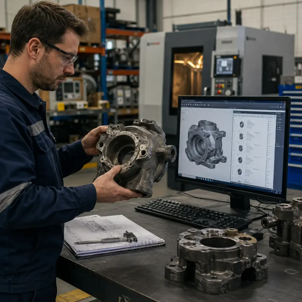
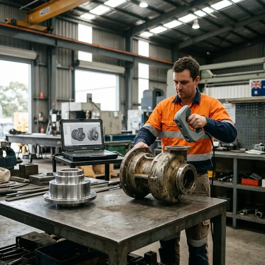
Industrial 3D scanning services in Australia allow engineering and manufacturing companies to capture the geometry of existing physical components and convert that information into usable digital data. When original drawings are missing, equipment is obsolete, or a component needs to be analysed or reproduced, 3D scanning can provide the starting point for a controlled reverse-engineering workflow.
For mining, manufacturing and other industrial operations, however, a scan is not the finished engineering model. Raw scan data typically needs to be cleaned, interpreted and reconstructed into CAD before it can support modification, inspection or manufacturing. The distinction between 3D scanning, scan-to-CAD and reverse engineering is therefore critical.
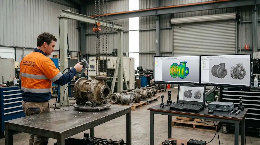
A typical industrial workflow can move from an existing component through scanning and engineering reconstruction to a manufacturing-ready digital model:
Physical Component → 3D Scanning → Point Cloud / Mesh → Geometry Analysis → Reverse Engineering → CAD Model → Engineering Validation → Manufacturing
For Australian businesses dealing with legacy equipment, difficult-to-source components and long supply chains, this digital workflow can provide a practical path from a physical part to reusable engineering data.
What Is Industrial 3D Scanning?
Industrial 3D scanning is a non-contact measurement process used to capture the external geometry of a physical object. Depending on the scanning technology and application, a scanner records a large number of measurements across the component’s visible surfaces and uses them to create a digital representation.
Instead of manually measuring a complex component feature by feature, engineers can capture extensive surface geometry in a relatively short period.
This becomes particularly useful when dealing with components that contain freeform surfaces, complex transitions, cast geometry or features that would be difficult to reproduce accurately using conventional hand-measurement methods alone.
The initial output may take the form of a point cloud or polygon mesh representing the scanned surfaces.
That dataset can be extremely detailed, but it should not automatically be treated as a production-ready CAD model.
3D Scanning Is Not the Same as Reverse Engineering
The terms 3D scanning and reverse engineering are often used interchangeably, but they describe different stages of a digital engineering process.
3D scanning captures what physically exists.
Reverse engineering determines what the component was intended to be.
That difference becomes important when scanning industrial parts that have already spent years in service.
A worn pump component, for example, may have material loss around high-wear regions. A housing may be distorted. A mounting surface may have been damaged or repaired. Edges that were originally sharp may have become rounded through use.
An extremely accurate scan will capture these conditions accurately.
But manufacturing an exact copy of that scan could simply reproduce the wear and damage.
Reverse engineering requires engineering interpretation. The scan provides the geometric evidence; engineers then use that information to reconstruct design intent and develop an appropriate CAD model.
From a Physical Component to Scan Data
The quality of the final CAD model depends partly on how the physical component is captured.
Before scanning begins, engineers need to consider component size, surface condition, geometry, accessibility and the features that are important to the final application.
Reflective or difficult surfaces may require additional preparation depending on the scanning technology being used. Multiple scan positions may also be required to capture geometry that cannot be observed from a single direction.
Reference features and alignment strategies are particularly important where multiple datasets must be combined.
Once the required surfaces have been captured, the scan data can be processed into a digital representation of the physical component.
The objective at this stage is not to redesign the part. It is to obtain reliable geometric information from which the engineering process can continue.
What Is Scan-to-CAD?
Scan-to-CAD is the process of converting captured 3D scan data into a structured CAD model that can be used in an engineering environment.
This conversion is more involved than changing one file format into another.
A polygon mesh may represent the surface of a component, but conventional engineering workflows often require editable geometric features such as planes, cylinders, holes, radii, profiles and parametric dimensions.
During scan-to-CAD reconstruction, engineers interpret the scanned geometry and rebuild the component using appropriate CAD features.
The resulting model can then be used for activities such as dimensional analysis, component modification, assembly integration, simulation, technical documentation or manufacturing preparation.
This is one reason industrial 3D scanning services are most valuable when scanning capability is combined with engineering expertise.
The objective is not merely to produce a digital image of a part. It is to produce data that can support the next engineering decision.
Reverse Engineering Components Without Original CAD
Industrial equipment can remain operational for decades, while its original engineering data does not always remain equally accessible.
A company may have a functioning physical component but no CAD file. The original manufacturer may no longer support the equipment. Drawings may be incomplete, or a replacement component may have an unacceptable procurement lead time.
In these situations, the existing component can become the starting point for rebuilding the missing digital information.
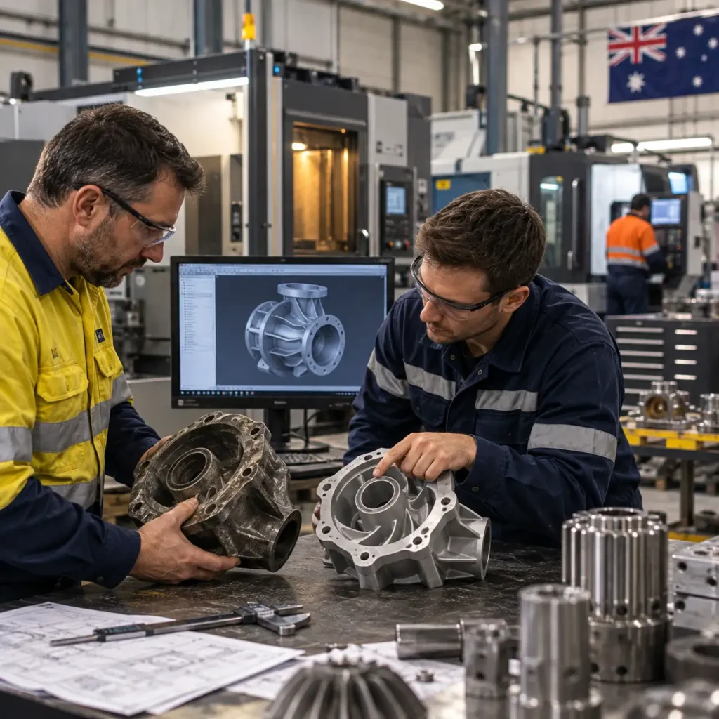
The workflow may begin by scanning the part and identifying its important geometric features. Engineers can then reconstruct the component in CAD while considering nominal dimensions, symmetry, mating interfaces and evidence of wear or modification.
Where appropriate, conventional measurement methods can also be used alongside 3D scanning to verify critical features.
The result is not simply a scan of an old component. It is a reconstructed engineering model that can potentially support future inspection, redesign or manufacturing.
How Accuracy Should Be Considered in Industrial 3D Scanning
A common question is:
How accurate is 3D scanning?
There is no useful universal answer without understanding the application.
Required accuracy depends on the component, scanner, scanning volume, surface condition, setup, environment and the feature being measured. More importantly, not every surface on an industrial component necessarily requires the same tolerance.
A decorative external contour and a precision bearing interface, for example, perform very different functions.
A good scanning strategy therefore begins by understanding what the digital model will be used for.
If the objective is reverse engineering, engineers need to identify which dimensions and interfaces are functionally critical. If the objective is inspection, the measurement strategy needs to reflect the tolerances being evaluated.
This is why an industrial scanning project should not be judged solely by the number of points collected or the nominal specification of a scanner.
The measurement needs to be appropriate for the engineering requirement.
Comparing Scan Data with an Existing CAD Model
3D scanning is also useful when the original CAD model already exists.
Instead of reverse engineering a missing model, scan data can be compared against nominal CAD geometry to investigate dimensional deviation.
This can help engineers visualise where a manufactured or worn component differs from its digital reference.
A typical inspection workflow may look like:
Physical Part → 3D Scan → Alignment with CAD → Deviation Analysis → Engineering Review
Colour-map deviation analysis can make geometric differences easier to identify across complex surfaces.
Depending on the measurement requirements and validation process, this type of analysis can support manufacturing inspection, wear assessment, prototype evaluation and investigation of component deformation.
For industrial applications, the value lies in turning a complex physical surface into measurable digital information.
3D Scanning for Mining Components
Mining is one of the Australian industries where this workflow can be particularly useful.
Equipment often operates in remote locations under abrasive, high-load conditions. Components can remain in service for long periods, and replacement parts for older equipment may become difficult to source.
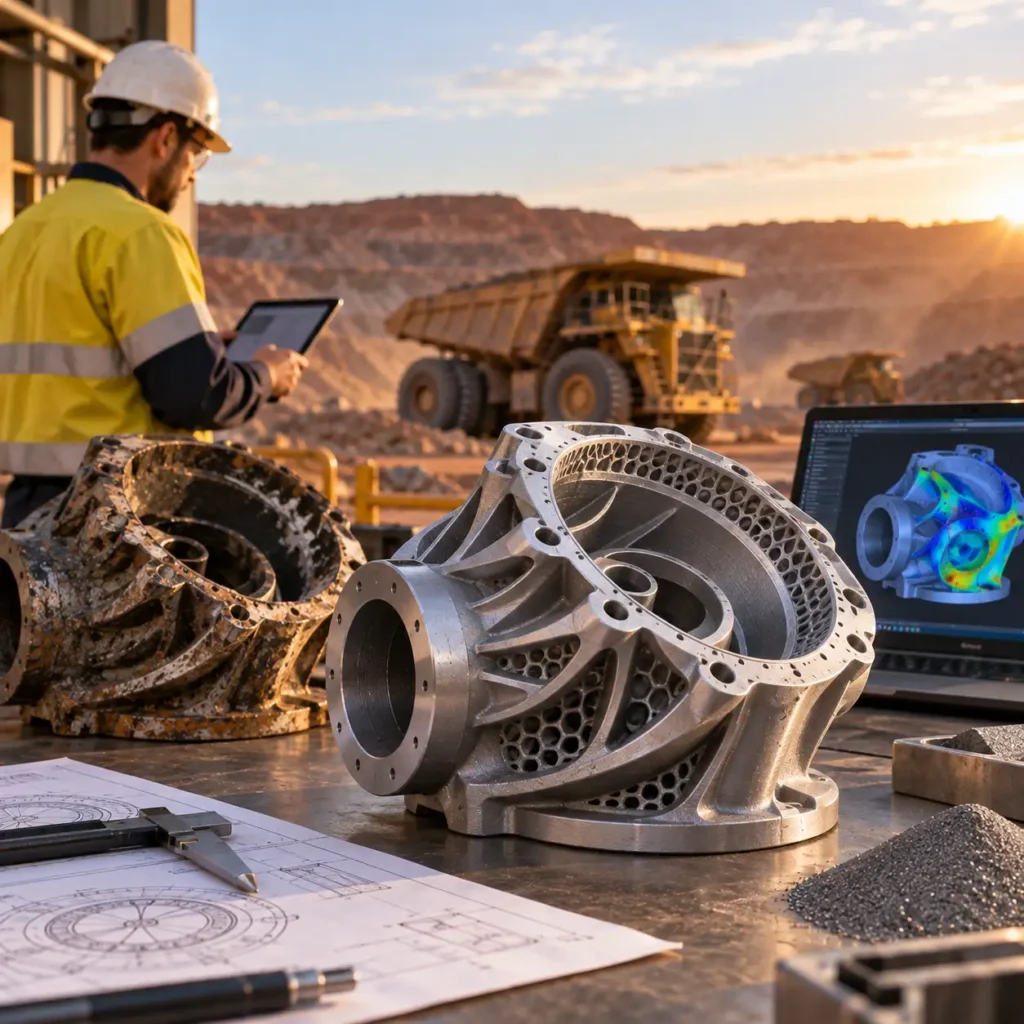
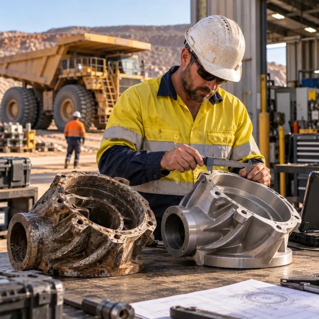
Consider a worn pump housing or specialised equipment component for which no usable CAD data is available.
Instead of beginning with manual drawings alone, the physical component can be scanned to capture its geometry. Engineers can then reconstruct the part in CAD, identify areas affected by wear and determine the intended geometry of critical features.
At this point, several options become possible.
The component could be reproduced using an appropriate conventional manufacturing method. It could be modified to address an engineering issue. Or, where technically and economically suitable, it could be assessed for metal 3D printing.
This is where 3D scanning becomes part of a larger digital manufacturing strategy rather than an isolated measurement service.
From Worn Mining Part to Optimized Replacement
Reproducing an obsolete component is not always the same as solving the problem that caused it to fail.
Suppose a mining component repeatedly experiences damage around a particular region.
Scanning the damaged component and manufacturing an identical copy could reproduce the same underlying weakness.
A more valuable workflow may be:
Worn Component → 3D Scan → Reverse Engineering → Failure Assessment → Design Optimization → Validation → Manufacturing
Once the component exists as an editable CAD model, engineers can investigate whether a justified design modification could improve its performance.
Finite Element Analysis may be used to examine structural behaviour under defined loading conditions. Geometry may be modified to address a stress concentration. Material selection or manufacturing strategy may also be reconsidered.
This links industrial 3D scanning directly with design optimization for mining components.
The physical part provides the starting information, but the digital model creates the opportunity to improve it.
3D Scanning for Australian Manufacturing
The same principles extend well beyond mining.
Australian manufacturers may need digital models of legacy tooling, machine components, fabricated structures, prototypes or parts supplied without usable CAD data.
Industrial 3D scanning can help capture complex geometry for further engineering work without requiring every feature to be reconstructed from manual measurements.
For product development, an existing physical prototype can be digitised and brought back into a CAD workflow.
For legacy equipment, a physical component can provide the geometric basis for replacement engineering.
For manufactured components, scan data can support comparison with nominal geometry.
The important point is that 3D scanning does not determine the manufacturing process.
Once usable engineering data has been created, the appropriate production route might be CNC machining, fabrication, casting, metal additive manufacturing or another process.
The engineering and commercial requirements should determine that decision.
3D Scanning and Metal Additive Manufacturing
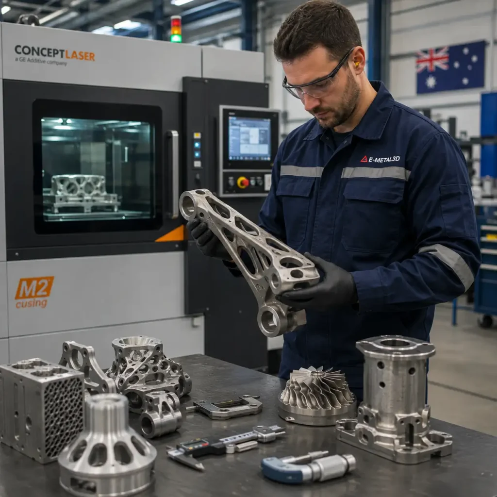
3D scanning and metal additive manufacturing are complementary technologies, but they solve different problems.
Scanning converts physical geometry into digital information.
Metal additive manufacturing converts digital geometry into a physical component.
Reverse engineering connects the two.
This creates a digital loop:
Physical Part → Digital Capture → Engineering Model → Manufacturing → Physical Part
For suitable components, this workflow can be particularly useful where conventional tooling is unavailable, production quantities are low or the geometry presents an opportunity for additive manufacturing.
However, simply obtaining a scan does not make a component suitable for metal 3D printing.
Material requirements, component size, geometry, mechanical performance, tolerances, surface finish, post-processing, inspection requirements and economics must all be considered.
The manufacturing method should therefore be selected after engineering assessment rather than predetermined at the scanning stage.
Building a Digital Spare Parts Library
One of the longer-term opportunities created by industrial 3D scanning is the development of digital spare-parts information.
Traditional spare-parts strategies rely heavily on physical inventory. That remains essential for many critical and frequently consumed components, but storing every low-volume or obsolete part indefinitely can be inefficient.
Selected components can instead be digitised before they become urgently required.
A company might capture the physical component, reconstruct the engineering model, record relevant manufacturing information and retain the validated digital data for future use.
This creates the foundation for a digital spare parts inventory.
When a suitable component is required in the future, the organisation is no longer starting with an unidentified physical object and no engineering data.
The digital foundation already exists.
For Australian mining and industrial businesses operating across large geographic distances, this approach can support a more resilient spare-parts strategy when applied selectively.
Supporting Local and On-Demand Manufacturing in Australia
Australia’s geography can make industrial supply chains challenging, particularly when specialised components need to travel long distances or come from overseas suppliers.
A digital engineering workflow changes where some of that work can occur.
If a component has been properly scanned, reverse engineered and validated, its engineering data can support manufacturing closer to where the part is required, provided the selected manufacturing process and supplier can meet the necessary requirements.
This does not mean every component should be manufactured locally or on demand.
For standard, inexpensive and readily available parts, established supply chains may remain the most efficient solution.
The opportunity is strongest for selected components where long lead times, obsolescence, low production quantities, custom geometry or downtime costs create a strong reason to consider another approach.
In these cases, industrial 3D scanning can be the first step toward on-demand manufacturing in Australia.
When Should a Company Consider Industrial 3D Scanning?
Industrial 3D scanning is particularly valuable when a physical object contains geometric information that needs to be brought into a digital engineering workflow.
Common situations include an obsolete component with no CAD data, a complex surface that is difficult to measure manually, a legacy part that needs to be redesigned, a prototype that needs to be digitised or a manufactured component that needs to be compared with its nominal geometry.
It can also be useful when building a digital inventory of selected spare parts.
However, scanning is not automatically the most appropriate measurement method for every engineering task.
Simple components may be faster to measure conventionally. Certain critical dimensions may require complementary metrology methods. Internal geometry may also require a different inspection technology if it cannot be observed by the selected scanner.
The correct approach depends on what needs to be captured and why.
Choosing an Industrial 3D Scanning Service in Australia
For engineering applications, choosing a 3D scanning provider should involve more than comparing scanner specifications.
The important question is what happens after the scan.
Can the provider interpret worn geometry? Can they reconstruct an editable CAD model? Can they identify the difference between measured geometry and intended geometry? Can the resulting model be prepared for engineering analysis or manufacturing?
For companies that ultimately need a replacement component, the ability to connect scanning with reverse engineering, design optimization and manufacturing can simplify the workflow.
Instead of treating scanning as the final deliverable, it becomes the first stage of a broader engineering process.
That distinction is particularly important for industrial projects where the end objective is not a point cloud—it is a usable engineering outcome.
From Physical Parts to Manufacturing-Ready Engineering Data
Industrial 3D scanning gives Australian businesses a practical way to recover digital information from existing physical assets.
Its real value, however, appears when that information moves beyond the scan itself.
A point cloud can become a mesh. A mesh can support reverse engineering. Reverse engineering can create an editable CAD model. That model can then support inspection, redesign, simulation or manufacturing.
For mining companies, manufacturers and engineering teams managing legacy equipment, obsolete components or complex geometry, this creates a bridge between existing physical assets and modern digital manufacturing.
The objective is not to scan everything.
It is to identify the components where capturing and preserving engineering data can reduce future uncertainty, improve engineering decisions and create more manufacturing options.
For projects that require this complete workflow, E-Metal3D’s 3D scanning services can support the transition from physical component capture through reverse engineering and engineering preparation for an appropriate manufacturing route.
What are industrial 3D scanning services?
Industrial 3D scanning services capture the surface geometry of physical components and convert it into digital data. The resulting point cloud or mesh can then support reverse engineering, scan-to-CAD, inspection, redesign or manufacturing workflows.
Can 3D scanning create a CAD model?
3D scanning provides the geometric data required to create a CAD model, but the raw scan itself is generally not equivalent to an editable engineering CAD model. Scan-to-CAD or reverse engineering is typically required to reconstruct usable CAD geometry.
Can a part be reverse engineered without the original drawings?
Yes. Where suitable physical geometry is available, 3D scanning and complementary measurement methods can provide the information needed to reconstruct a CAD model. Engineers still need to interpret wear, damage, tolerances and design intent.
Can worn or damaged components be 3D scanned?
Yes, but the scanner will capture the worn or damaged geometry that physically exists. Reverse engineering is required to determine which features represent the intended component geometry and which represent wear or damage.
How accurate is industrial 3D scanning?
Accuracy depends on the scanning technology, component size, surface properties, setup, environmental conditions and measurement requirements. The required accuracy should therefore be defined according to the engineering application rather than assumed from a single scanner specification.
What is the difference between 3D scanning and scan-to-CAD?
3D scanning captures physical surface geometry. Scan-to-CAD converts that captured information into structured CAD geometry that can be edited and used within engineering and manufacturing workflows.
Can 3D scanning be used for mining spare parts?
Yes. It can be particularly useful when a mining component is obsolete, difficult to source or no longer has usable CAD data. The captured geometry can support reverse engineering, engineering assessment and selection of an appropriate manufacturing method.
Can a scanned component be metal 3D printed?
Potentially. The component must first be reconstructed into suitable digital geometry and assessed for additive manufacturing. Material, size, tolerances, mechanical requirements, post-processing, inspection and economics all influence whether metal 3D printing is appropriate.
What industries can use industrial 3D scanning in Australia?
Industrial 3D scanning can support mining, manufacturing, engineering, energy and other sectors where existing physical components need to be digitised for inspection, reverse engineering, redesign or manufacturing.